This thread has been locked.

If you have a related question, please click the "Ask a related question" button in the top right corner. The newly created question will be automatically linked to this question.

P82B715: Unable to read data via P82B715

Part Number: P82B715
Other Parts Discussed in Thread: P82B96

Hi,

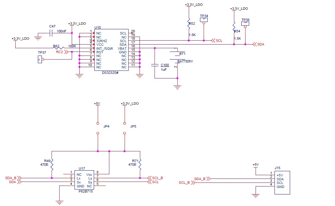
I'm trying to read the inclination angle from my inclinometer, my main board(MCU) is connected to accelerometer (located on daughter board) via a 1 meter (4 core shielded) cable, as shown in below attached document. The schematics of the connectivity of MCU, I2C buffer, RTC IC (excluding cable & Inclinometer) are present in the last page of the attached word document, please refer.

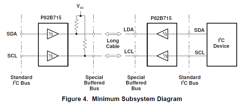
U17---> I2C buffer (P82B715)

U10--->RTC IC (DS3232SN#)

When I tried to read the inclination angle, I'm getting as "Inclinometer Error" on putty as shown in attached image for not working board. But with the same cable I'm able to read correct data using another working board, there I'm able to see the (X-axis) angles, please go through the images attached. So I guess there is no issues with the cable & daughter card. I've checked continuity & parts around the U10, U17 ICs they are fine.

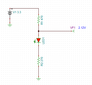
I2C buffer & RTC IC are sharing the common I2C bus from MCU. I've measured the voltages at SDA, SCL pins of U10 IC, then I got 2.1V around. Then I tried to measure SDA, SCL pin voltages at RTC IC, by removing U17(P82B715) IC, then I got around 3.1V on them. So then I replaced with new P82B715 IC , but now I got 2.1V. I am getting "??" symbols while tried to input time to RTC IC due to this I guess.

All the other working boards are pulled to 3.3V only, i'm able to get valid X-axis values on putty.

I have measured the voltages on U17 IC at SDA, SCL, LX, LY pins of working & not working boards using Oscilloscope, please find them in attachments, similarly for U10 IC measured SDA, SCL both working & not working boards.

Please suggest me how to proceed.

All the required images are placed in the attached MS Document file, please go thorugh.

2870.I2C Issue.docx

Thank you in advance.

  • Hey Rahul,

    I'm pretty sure the reason you are seeing 2.1V on the line and 3.3V when you remove the P82B96 is because you are measuring the voltage at net name SDA and net name SCL and not net name SDA_B and SCL_B. The reason for the high signal being 2.1V is likely because of the LED and 270 ohm resistor to GND. You effectively have a resistor divider between the 470 ohm pull up, LED and 270 ohm pull down. If you want to generate LEDs for SDA_B/SCL_B you should use an NFET and tie the gate to the SCL_B/SDA_B to make the connection high impedance and get rid of the resistor divider.

    Here you can see the source of the 2.1V issue.

    The second thing I see which could be causing a problem is you are only using one P82B715, this device is meant to be used in a pair like the datasheet shows:

    If you only use one of them with a 470 ohm pull up resistor, in the worst case you are allowing 7mA as your IoL at 3.3V and 10.6mA at 5V when the master/slave pulls low. This could be enough to break/damage the NFET of your master/slave on SDA and SCL. Using two P82B715s allow for them to take the large current hits instead of the master/slave.

    My recommendation is to remove the LED and pull down resistor and then size up the pull up resistor to be ~2k on both sides and slow your clock frequency down if you can to make communication a bit easier (pull ups don't need to be strong when you make your I2C clock slower).

    Let me know if this resolves the issue you were having. If not we can try to debug further.

    -Bobby

  • Hi Bobby,

    Thank you for your response.

    I'm Sorry, there should not be LEDs & 270E pull downs in the schematic at the connector J15, I forgot to remove them from the Schematics. Now I should see around 3V at SCL & SDA pins (pulled up to 3.3V through 470E) of U17  right?, but still 2.1V as mentioned above in the Not working board. But on the other working boards I'm able to see 3V around on SCL & SDA pins with the same connections. 

    I'm using P82B715 on both at Master(MCU) & Slave(Inclinometer) ends, so there should not be any I guess. We have replicated the connections of P82B715  at Slave, similar to that of master


    Updated schematics is attached below please find, Now please help me on this.

  • Hey Rahul,

    "I'm using P82B715 on both at Master(MCU) & Slave(Inclinometer) ends, so there should not be any I guess. We have replicated the connections of P82B715  at Slave, similar to that of master"

    Your picture shows the mcu is connected directly to the daughter board P82B715. I just want to verify, your actual connection is:

    MCU------P82B715-->------1M Cable-------<-P82B715-------Inclinometer

    ^^Is this correct?^^

    "Now I should see around 3V at SCL & SDA pins (pulled up to 3.3V through 470E) of U17  right?"

    Yes, while the bus is idle, the voltage should be close to 3.3V

    If you are seeing 2.1V on the rail and removing the P82B715 lifts it back up to 3.3V then I suspect the device may have been damaged.

    A good way to tell if the problem is the specific device is to remove the bad device and solder it on a good board and see if the problem follows the device or the board. We call this an A-B-A test in the industry. Were you able to perform this test with the known bad unit?

    When you connect the daughterboard to the main board, are you doing so while the mainboard is powered up? (Hot Insertion) Or are they both unpowered when you connect then power them up?

    The only other source of damage I can think of is potential ESD damage if proper IC handling procedures were not used when soldering and working with it on the bench.

    -Bobby

  • Hi Bobby,

    "MCU------P82B715-->------1M Cable-------<-P82B715-------Inclinometer  "

    Yes, whatever you have drawn is correct.

    "Yes, while the bus is idle, the voltage should be close to 3.3V"

    I have measured the voltages, while reading the inclinometer values only. When the bus is idle, then also I'm getting 2V on both SDA & SCL pins of U17. I've tride by replacing the 470E pull-up with 1.5K , still 2V only.

    "When you connect the daughterboard to the main board, are you doing so while the mainboard is powered up? (Hot Insertion) Or are they both unpowered when you connect then power them up?"

    Daughter board is connected to main board, then only powering them up.

    I've tried by replacing new P82B715 IC on the Not working board, still I 'm getting 2V at SDA & SCL of U17 IC (with bus in idle state or while reading, values from inclinometer).  So I have tried as you have suggested. Mounted the IC from not working board to working board, now I'm getting the values. Similarly mounted the IC from Working board to Not working board, unable to read the values. As you you have said, it could be problem with the board itself. 

    I want to know the root cause of the above issue, any guess please.

    Thank you so much for your time & support, I really appreciate it. 

  • "I've tried by replacing new P82B715 IC on the Not working board, still I 'm getting 2V at SDA & SCL of U17 IC (with bus in idle state or while reading, values from inclinometer).  So I have tried as you have suggested. Mounted the IC from not working board to working board, now I'm getting the values. Similarly mounted the IC from Working board to Not working board, unable to read the values. As you you have said, it could be problem with the board itself. "

    It sounds like the problem isn't with the P82B715 since the problem doesn't follow the device. I would suggest removing one component from the not working board at a time and measuring the Idle SCL/SDA levels on an o-scope to see when the signal goes back to 3.3V. Either one of the other ICs on the not working board is damaged or there may be an actual problem with the board.

    Also triple check and make sure all devices on the not working board are soldered on correctly. Sometimes I see customers accidently populate ICs 180 degrees out of place. Typically the top side of an IC will either have a line on the top to indicate pin 1 or will have a dot on the top left hand side.

    A side from this I would maybe triple sure the LEDs are not populated on the not working board again to be sure.

    Thanks,

    -Bobby

  • Hello Bobby,

    Thank you so much for the suggestion, you saved my board.

    There was discontinuity for the SCL in the signal path, I've corrected it, now it's working fine.

    Thanks a lot Bobby.