This thread has been locked.

If you have a related question, please click the "Ask a related question" button in the top right corner. The newly created question will be automatically linked to this question.

SN65DSI86: Semi-Auto link training successfully for RBR, but HBR - fail

Part Number: SN65DSI86
Other Parts Discussed in Thread: TEST2

Hello, dear TI

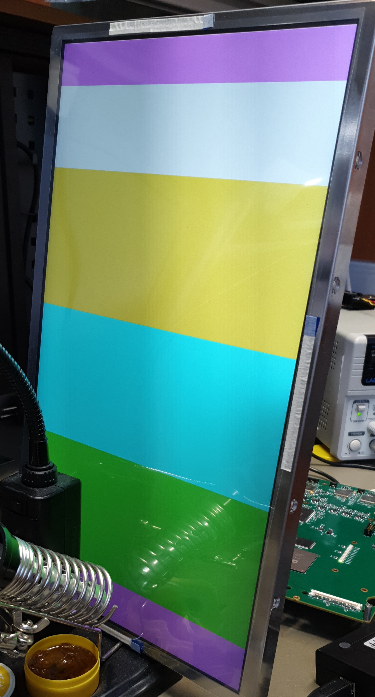
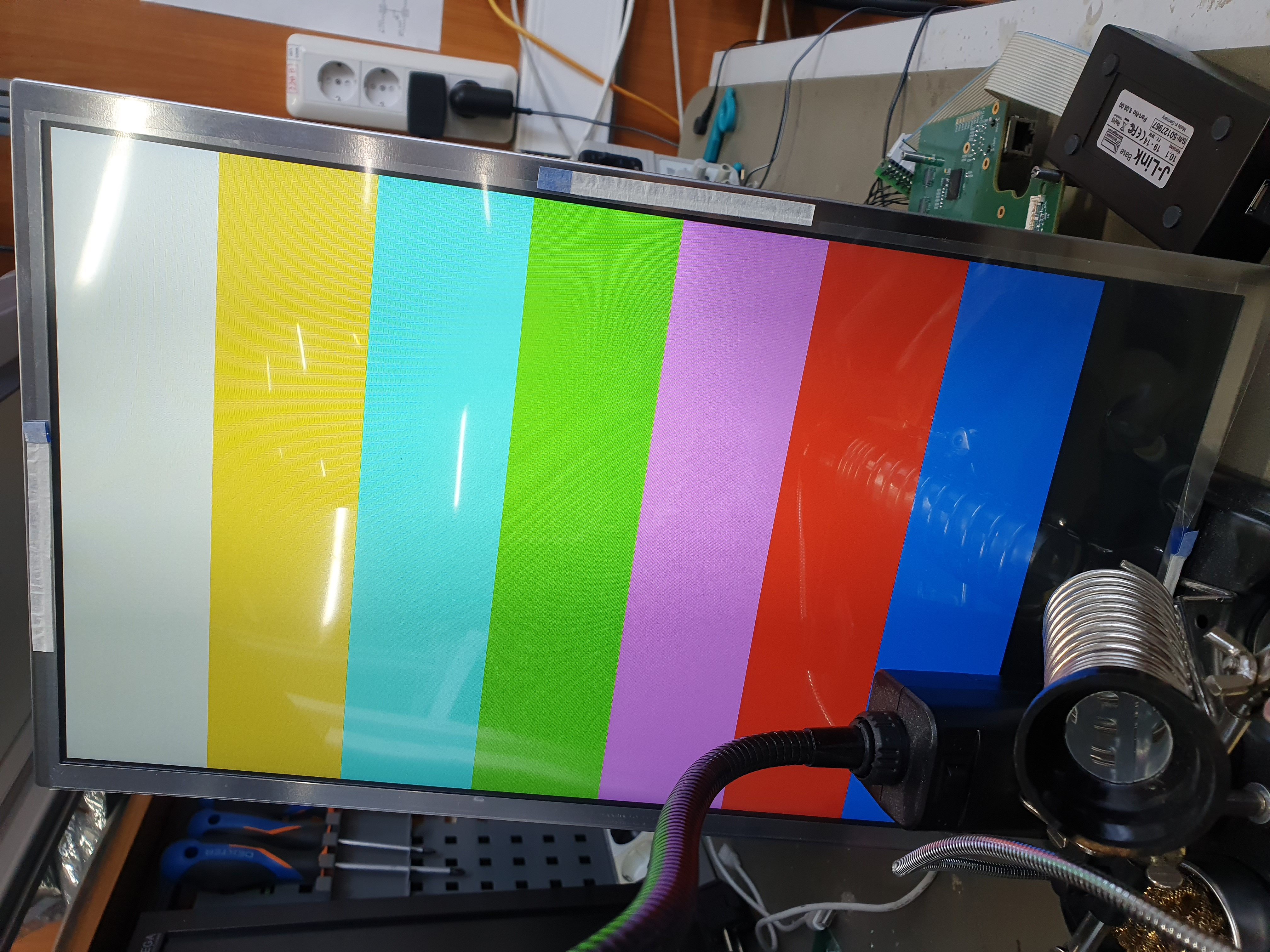
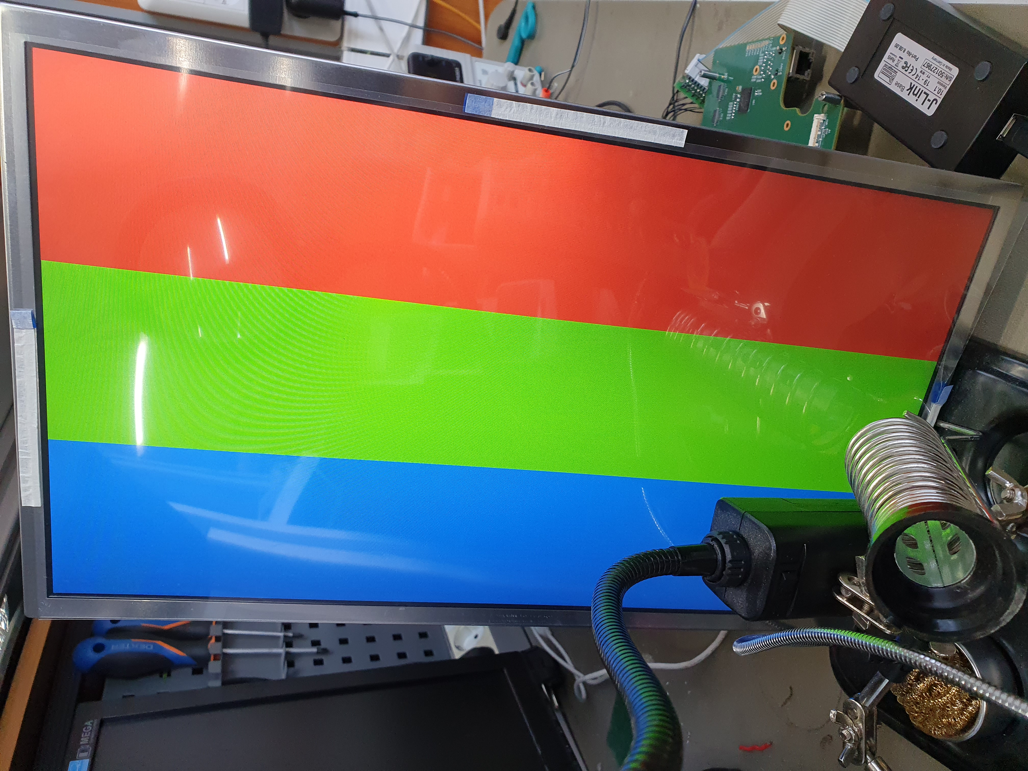
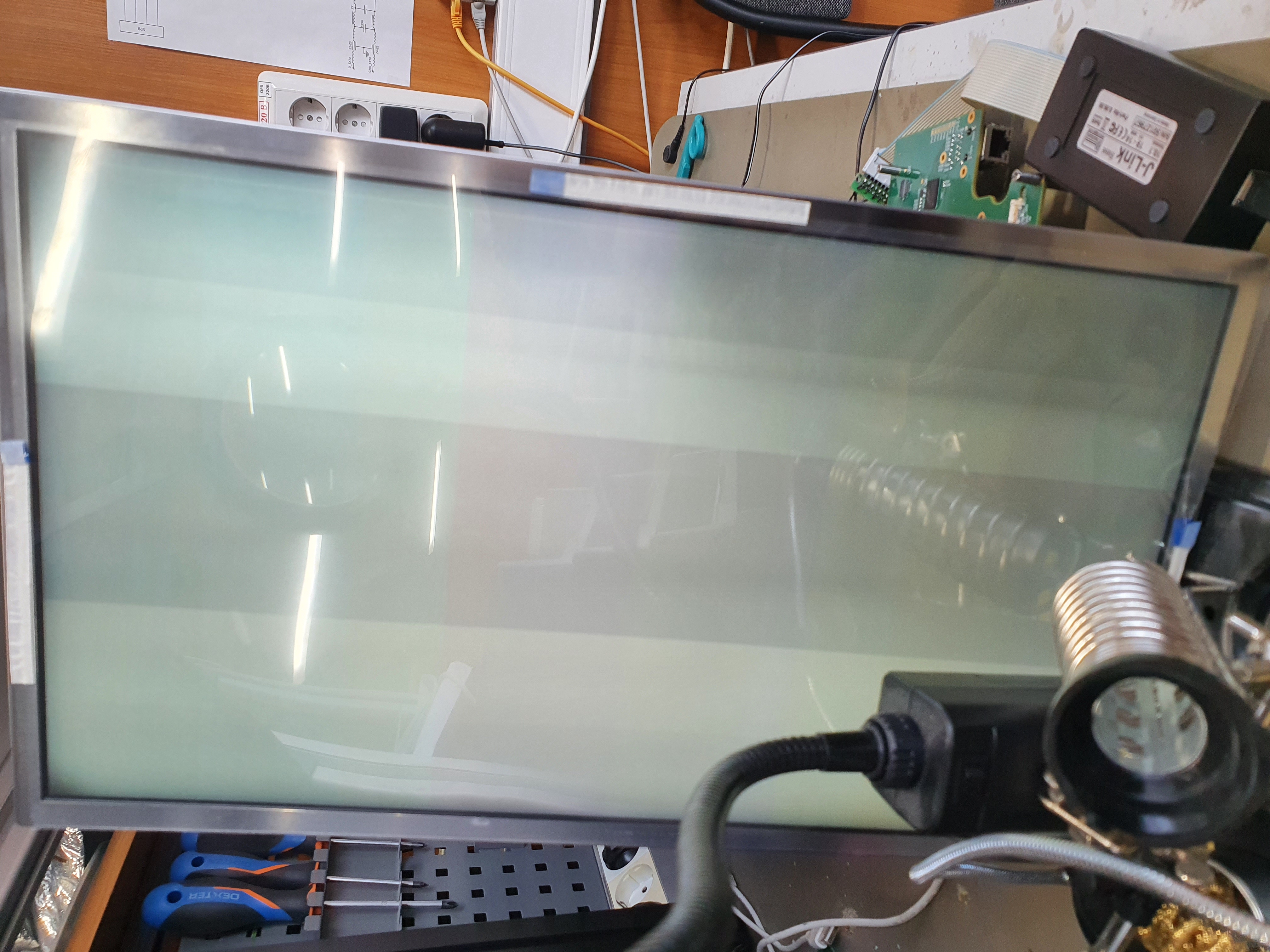
I try to connect my LCD panel with two lanes of main link and 16M color deep to DSI86. I get all calculations from PANEL_VIDEOREGISTER_CALC based on EDID. In this sheets I choose  DSI Video mode "RGB666" and get "optimum data rate" - RBR.

I programmed the registers according to the script and start Semi-Auto link training and get success. But in panel's datasheet specified datarate as 2.7Gbp/s which Semi-Auto link training returned fail.

Related quastions:

1 May I use for my panel 1.62Gbps datarate and RGB666 color deep instead 2.7Gbps and RGB888 color deep ? RGB666 enough for me

2 Will it work, if I forcefully choose HBR, and ignore result of Semi-Auto link training?

Thanks!

  • Hi,

    Please check panel's datasheet, the 2.7G is probably panel's max supported data rate. If this is the case, then the panel will support both 1.62 and 2.7G data rate.

    For HBR, you need to change the DSI86 DP_DataRate in register 0x94 and make sure the link training is successful at 2.7G.

    Thanks

    David

  • Thank you for your reply, David

    I use panel NL192108BC18-06F. Using the i2c-over-aux I received EDID:

    00 ff ff ff ff ff ff 00 39 94 00 00 00 00 00 00 
    00 19 01 04 a5 00 00 78 00 00 00 00 00 00 00 00 
    00 00 00 00 00 00 01 01 01 01 01 01 01 01 01 01 
    01 01 01 01 01 01 1a 36 80 a0 70 38 20 40 40 30 
    36 00 58 c2 10 00 00 18 00 00 00 0f 00 20 20 20 
    20 20 20 20 20 20 20 20 20 20 00 00 00 0f 00 20 
    20 20 20 20 20 20 20 20 20 20 20 20 00 00 00 0f 
    00 20 20 20 20 20 20 20 20 20 20 20 20 20 00 81

    And based this data I get my script:
    ======REFCLK Frequency  ======
    <i2c_write addr=0x2D count=1 radix=16> 0A 6 </i2c_write>/>

    ======DP Datarate  ======
    <i2c_write addr=0x2D count=1 radix=16> 94 20 </i2c_write>/>

    ======Enable PLL  ======
    <i2c_write addr=0x2D count=1 radix=16> 0D 1 </i2c_write> <sleep ms=10/>

    ======Enable enhanced frame  in DSI86  ======
    <i2c_write addr=0x2D count=1 radix=16> 5A 4 </i2c_write>/>

    ======Number of DP lanes  ======
    <i2c_write addr=0x2D count=1 radix=16> 93 20 </i2c_write>/>

    ======Start Semi-Auto Link Training  ======
    <i2c_write addr=0x2D count=1 radix=16> 96 0A </i2c_write> <sleep ms=20/>

    ======CHA Active Line Length  ======
    <i2c_write addr=0x2D count=2 radix=16> 20 80 07 </i2c_write>/>

    ======CHB Active Line Length  ======
    <i2c_write addr=0x2D count=2 radix=16> 22 0 0 </i2c_write>/>

    ======Vertical Active Size   ======
    <i2c_write addr=0x2D count=2 radix=16> 24 38 04 </i2c_write>/>

    ======Horizontal Pulse Width   ======
    <i2c_write addr=0x2D count=2 radix=16> 2C 30 00 </i2c_write>/>

    ======Vertical Pulse Width   ======
    <i2c_write addr=0x2D count=2 radix=16> 30 06 00 </i2c_write>/>

    ======HBP   ======
    <i2c_write addr=0x2D count=1 radix=16> 34 30 </i2c_write>/>

    ======VBP   ======
    <i2c_write addr=0x2D count=1 radix=16> 36 17 </i2c_write>/>

    ===== HFP  ======
    <i2c_write addr=0x2D count=1 radix=16> 38 40 </i2c_write>/>

    ===== VFP  ======
    <i2c_write addr=0x2D count=1 radix=16> 3A 03 </i2c_write>/>

    ===== DP-18BPP Disable  ======
    <i2c_write addr=0x2D count=1 radix=16> 5B 0 </i2c_write>/>

    ===== Color Bar Enable  ======
    <i2c_write addr=0x2D count=1 radix=16> 3C 0F </i2c_write>/>

    ===== Enhanced Frame, and Vstream Enable  ======
    <i2c_write addr=0x2D count=1 radix=16> 5A 0C </i2c_write>/>

    </aardvark>

    After execution that, I get "1" in 0xF8 register. Then I try to set data rate to 2.7Gbps, and get the 0x12 in register 0xF8. In both cases I have dark screen on my Panel. Also, no changes in current consumption occurs. Level 3 in LUT registers are enabled.

    What should I do for run video stream ? May I bypass the Link Train?

    Could this Link Train fail be due to impedance mismatch?

    Thanks!

    UPD:

    I found error in script above:

    ===== Color Bar Enable  ======
    <i2c_write addr=0x2D count=1 radix=16> 3C 0F </i2c_write>/>

    It's must be 3C 1F.
    At speed 1.62G I can see color bars, horisontal bars - ok, but vertical bars , it seems to be whrong, they are unevenly displaced. What could have caused this?
    At speed 2.7G I'm still see nothing. How to force link up without train?

  • Hi.

    1. For 1.62G, have you tried to enable the color bar and see if the color bar works? To enable color bar, 

    Register 0x3C, set bit 4 to 1, and set [2:0] to the color bar pattern

    2. If the color bar does not work, please pull TEST2 pin high and run the "Disable ASSR" script.

    3. If 1.62G works, then switches to 2.7G. Please keep in mind that changes in data rate will cause the DP PLL to lose lock. SW should always wait until DP_PLL_LOCK bit is set before attempting another Semi-Auto Link training.

    Thanks

    David

  • 1. Yes, I enabled the color bars, and they appeared on the screen. For horizontal 8 colors pattern - that's ok:

    But for vertical 8 color bars I see only 5 instead of 8, and some offset:

    How can I fix it? 18bpp mode enabled.

    2. ASSR is disabled.

    3. 1.62G works, I switched to 2.7G, wait for PLL lock and start Auto-Semi Link Training and get fail: 0x12 in register 0xF8. Please, help me undestend the reasons and ways to resolve this problem. 

    Thanks!

  • Hi,

    Value of 0x12 at register 0xF8 shows the DP link training failed at the equalization part of the training. This could be a signal integrity issue at 2.7G. You can change DSI86’s Link Training Look-Up-Table default values to see if it can help compensating the signal integrity issue. The LT LUT is located from register 0xB0 thru 0xC3. The LT LUT contains transmit voltage swing level and pre-emphasis levels used during the link training process.

    Does the color bar show up at 1.6G or 2.7G? Please refer to section 8.4.4.6 Video Format Parameters of the DSI86 datasheet. It looks like the panel parameters are not being programmed correctly.

    Thanks

    David

  • Hi! Thank you for your reply, David.

    > Does the color bar show up at 1.6G or 2.7G?

    1.62G, and it is works at 2.7G now. I solved my signal integrity problem and Semi-Auto Link Training is successful for both rate - 1.62G and 2.7G.

    I launched my panel at a speed of 2.7G and enabled the color bars.

    I see, that vertiсal bars are all ok, but when I enable horizontal bars I see flickering noise. Сan you tell me which video registers are configured incorrectly?

    Can I be sure that everything is okay with the physical lanes?

    UPD:

    I checked on all color bar patterns, and the problem only appears on the 8-color horizontal bars (COLOR_BAR_PATTERN = 0x4) or 8-grayscalse bars pattern (COLOR_BAR_PATTERN = 0x5). Other patterns display correctly

    1. Vertical 8 bars - ok

    2. Horizontal 3 bars - ok.

    3. horzontal 8 bars - fail. Somethings whrong ?

    It seems to me that color patterns 4, 5 work differently than patterns 0, 1, 2, 3, 6, 7. Since patterns 4,5 correctly displayed earlier at a speed of 1.62G, while others did not. But now, at speed 2.7G, all patterns are displayed correctly, except for 4, 5

    P.S. Please, sorry for my English

  • Are you seeing any errors being reported from register 0xF0 to 0xF8 with color bar setting 4 and 5? If you set color bar to 4 and 5, disable and then re-enable the color bar, does the color bar work correctly?

    What is the signal integrity issue you had at 2.7G?

    Thanks

    David

  • 1. No, I have no errors in registers 0xF0 to 0xF8. I tried to turn the color bars off and then on again, but it's still not work:

    // enable 0x4 color bars
    I2C::WriteExplicitSync(I2C_ADDR, 0x3C, 0x14);
    dumpIRQStatusRegs();
    
    // run stream
    I2C::WriteExplicitSync(I2C_ADDR, 0x5A, 0x0C);
    dumpIRQStatusRegs();
    
    // disable color bars
    I2C::WriteExplicitSync(I2C_ADDR, 0x3C, 0x04);
    dumpIRQStatusRegs();
    
    // enable color bars again
    I2C::WriteExplicitSync(I2C_ADDR, 0x3C, 0x14);
    dumpIRQStatusRegs();

    And here output for registers 0xF0 - 0xF8 respectively from "dumpIRQStatusRegs" function:

    Fx = { 00 00 00 00 00 02 00 00 01 }

    Fx = { 00 00 00 00 00 02 00 00 01 }

    Fx = { 00 00 00 00 00 02 00 01 01 }

    Fx = { 00 00 00 00 00 02 00 01 01 }

    I have the DPTL_DATA_UNDERRUN_ERR flag after disabling color bars. Is it normal?

    2. Impedance mismatch: It was a shield film on my FFC-cable. It increased the linear capacity and lowered the impedance below the permissible limit (35 Ohms instead of 50 Ohms single-ended). I removed the shield film and it worked.

  • Hi,

    The DPTL_DATA_UNDERRUN_ERR flag error is associated with DSI to DP video timing, and since color bar does not use DSI interface, the error being reported should be false.

    I expect the color bar pattern to be the same, and there is nothing special with color bar pattern 4 and 5. Do you have another FFC cable or panel you can try?

    Thanks

    David

  • Thank you for your help, David.

    I solved my problem. Patterns 4, 5 caused greater current consumption than the rest patterns and my power supply on the board was getting very noisy and it corrupted the main link signal waveform. I increased the power supply's filter capacity and it is work ok.

    I think this topic may be closed now. I may have questions in the future regarding DSI, I can ask them in a separate topic.