This thread has been locked.

If you have a related question, please click the "Ask a related question" button in the top right corner. The newly created question will be automatically linked to this question.

DP83867CS: State of MDIO signal

Part Number: DP83867CS

Hi All,

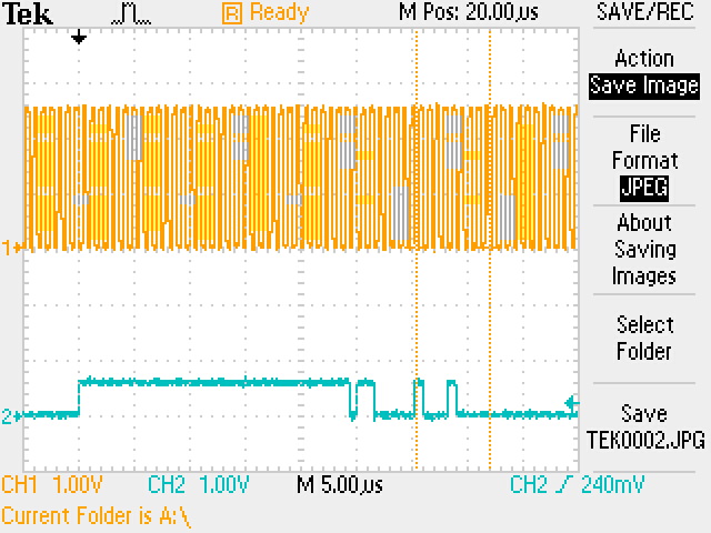
I have a new design using three DP83867CS PHYs and NXP T2081 MAC. I have the PHY addresses as 0, 1 & 2. The previous design used different PHYs but we changed them out to add additional functionality. The previous design PHY addresses were 1, 2 & 3. When we plug Ethernet cables in the PHYs appear to link up just fine. The problem is with the MDIO signal. It's very low, may .5V. It's pulled up with a 1.5K resistor. I double checked the schematic symbol, all pins numbers are correct, power etc. I've done dozens of Ethernet designs and have not seen this before. I was able to cut the PCB trace on MDIO on the last PHY and the signal level went up to about .9V. Both of our prototypes are doing the same thing.

My first question is, is PHY address 0 valid? I seem to read conflicting information on this. Any, any ideas? Has anyone seen this before?

Thanks!

  • Hi Lee,

    MDIO level should be VDDIO level for sure.What's the MDC clock frequency?

    Can you also please share the following :

    1. Snapshot of waveform during read operation (reading any phy register, to see if thats valid signal or just noise somehow).

    2. Snapshot of MDC waveform.(to confirm the level driven by controller)..appended with snapshot 1.

    3. Please share the snapshot of the schematic around phy.

    And yes 0x00 is the valid address.

    --

    Regards,

    Vikram

  • Here's the PHY address 0 schematic. I'll work on getting the wave forms.

    Thanks,

    Lee

    PHY 0.pdf

  • In the first waveform, this is after a power up or reset. MDC is low because there's a pull down in the PHYs. MDIO is pulled up to +2.5V as expected. At this point it looks like the MAC drives MDIO low and shortly after drives MDC high for the IDLE state. So, this looks good to me and it shows that MDIO can be pulled up to +2.5V.

    In the next capture, I triggered on MDIO, however look at the high state, it's about 600mV. It looks like a valid command, just way too low for any PHY to notice it. This is when U-boot is accessing the MAC/PHYs. The MAC should be controlling MDIO at this point as it's a command but it seems that one or more of the PHYs are in a states that is also driving it (low).

  • Hi Lee,

    MDIO should be high-z from Phy side untill the phy has to put some data on the line (ie when you try to read some register from phy and phy dumps the data on MDIO line). So it is highly unlikely that the phenomenon captured in the snapshots is because of phy's MDIO control as MAC is driving these signals.

    I dont see pull-up resistor on MDIO in schematic shared. Is it somewhere else? We will need that.

    --

    Regards,

    Vikram

  • This has been resolved. Our customer plans on using 1588 in the future so I used the GPIO signals as interrupts to the processor for start of frame detects. The signals are pulled up at the processor which caused the PHY reset strapping to be at incorrect voltages. Apparently, this put the PHYs in a undetermined state and must have been driving the MDIO signal low when it shouldn't have.