Part Number: TUSB9261
Hello,
I am working on a project for a customer including the TUSB9261. Currently, I have validated the power rails and have tuned them to meet the errata. Although Windows 10 (1903) picks it up, I receive a "Device Descriptor Error". Below is the activity that I see on the GPIOs:
- GPIO0 (FW Heartbeat) - This just stays low, never really makes an attempt to go high ever.
- GPIO1 (SS USB Link) - This is also low, although there was an attempt to link on the host device (Windows 10)
- GPIO2 (HS/FS Suspend) - This is again low.
- GPIO3 (Push-Button) - This is left as NC and is low as expected with Internal PD.
- GPIO4 (Bus or Self-Powered Indicator) - On original design, this was left as NC as we always wanted this to be on. Current rework has tried to PU to 3.3V w/ 4.7K as the 12V resistor divider puts it near that voltage. Does this need to be high from the 12V Source before 3.3V is available to the chip? This would ensure this has a stable input before the 3.3V/1.1V rails rise and are stable. If so this is a re-work that could be done.
- GPIO5 (SS USB Link State 1) - Oscilloscope shows this is low.
- GPIO6 (USB 2.0 Connection) - Oscilloscope again shows low.
- GPIO7 (USB SS Connection) - Oscilloscope shows Low.
- GPIO8 (UART Rx) - This was left as NC but probing the pin shows this pin as always high.
- GPIO9 (UART Tx) - This was left as NC but probing the pin shows this is always high.
- GPIO10 (Undefined) - This was left as NC have not probed this.
- GPIO11 (Power Fault Input) - Oscillscope shows this Voltage near ~400mV.
It's worth mentioning this includes the resistor divider for the USB Vbus. Additionally there is crystal activity and has been measured with high precision equipment to be in spec, so that part of the chip is alive. Additionally, all HSIO signals have been simulated and impedance control boards have been validated.
I am assuming that there is a power fault issue, although the only indicator I have is the 3.3V Slew rate is slower than the ~1.5ns rise and fall time requested by the datasheet. This was done to meet the errata requirements to have 1.1V be stable before 3.3V rises above its input high. Additionally I have manually used the reset pin to try and reset it but that also yields no luck.
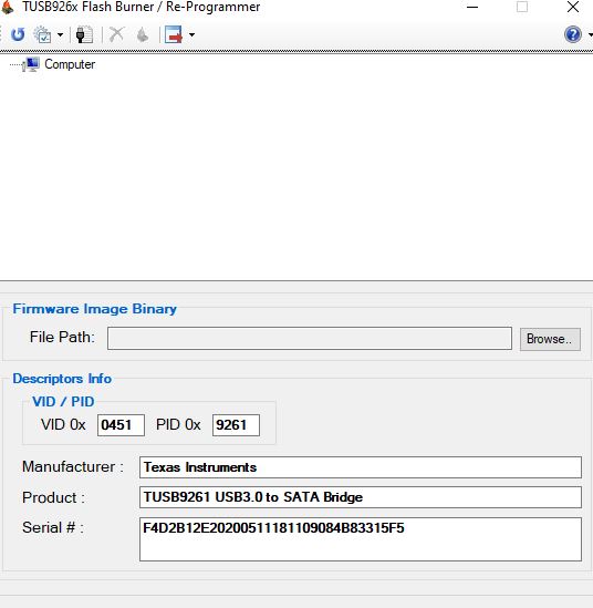
Finally, there is a SPI EEPROM wired up but it has no FW currently, I am unable to flash FW through it via the burner but it is a possibility to manually flash this using a Dediprog SPI flashing tool if this is believed to be the issue. Schematics and Layout are available for review as well.
Thank you,