This thread has been locked.

If you have a related question, please click the "Ask a related question" button in the top right corner. The newly created question will be automatically linked to this question.

TUSB2046B: Crystal selection and schematic review

Part Number: TUSB2046B

Hi,

I'm designing a board and I'm placing the TUSB2046BVFR USB HUB.

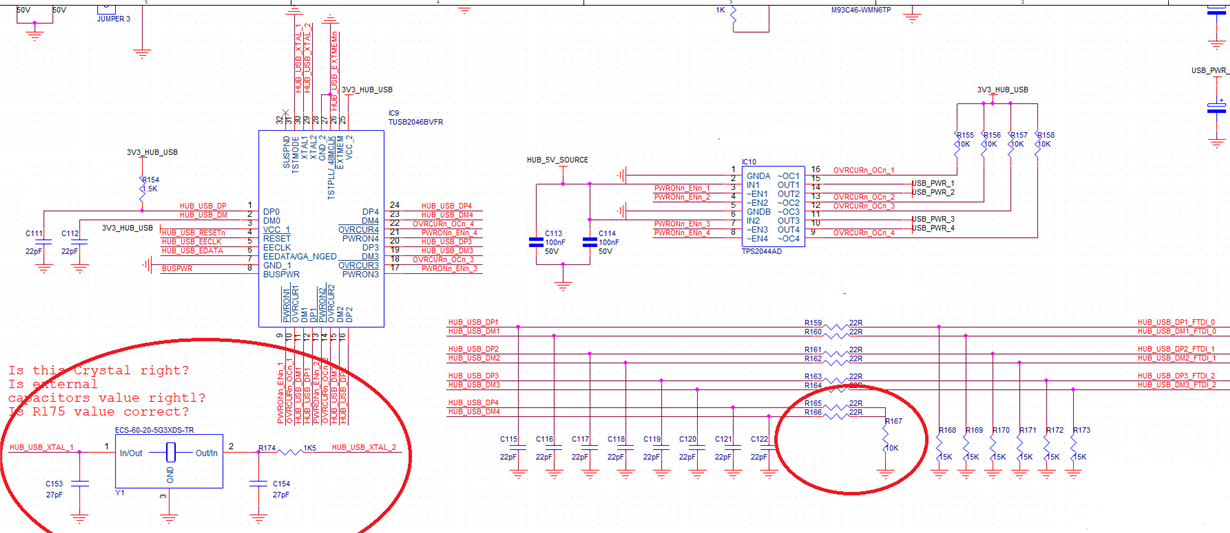
The crystal suggested by datasheet is not simple to be found. Could you please provide me an active crystal PN giving me please the capacitors values?

I have many doubts. I enclose the schematic. Could you please do a review? There are many answers in red.

Thank you.

Ste8233.USB_HUB.pdf

  • Hi Stefano,

    Schematic feedback below:

    • Please be aware that the TUSB2046B is a USB Full Speed hub only (12 Mbps, not 480 Mbps).
    • The 22 ohm series resistors are required.
    • No ESD on internally connected ports is necessary.
    • HUB_USB_PWR should not be directly connected to the BUSPWR input.  The BUSPWR input is only a configuration input that determines how the hub reports itself to the host controller.  It cannot tolerate 5V.
    • Typically there is a bulk capacitor on the VBUS on the upstream port, of between 1 uF to 10 uF.
    • The external memory is not required for the TUSB2046B.
    • A 6MHz crystal circuit requires capacitors similar to Figure 6 in the datasheet.
    • You can select a fundamental mode 6 MHz crystal with low ESR (50 ohms) and good frequency stability (50 ppm) and tolerance (50 ppm) and it will provide the necessary Cl values.

    Regards,

    JMMN

  • HI JMMN,

    thank you for your response,

    Some more question:

    1. I changed the crystal to be compliant with DS. Is the ECS-60-20-5G3XDS-TR right ? (see the link: https://www.mouser.it/ProductDetail/ECS/ECS-60-20-5G3XDS-TR?qs=%2Fha2pyFaduh0SKl7ZwU64tnQVxn780U8F7GCbQe9nmA%3D )

    2. Are the capacitor and resistor correct? (See the capacitors DS: https://www.mouser.it/ProductDetail/Murata-Electronics/GCM0335C1E270JA16D?qs=5aG0NVq1C4zWgMRiLd7Qiw%3D%3D)

    3. Downstream Port 4 (DM4 and DP4) is unused. Is it correctly terminated?

    See the picture enclosed.

    BR.

    Stefano

  • HI Stefano,

    Yes, that crystal and circuit look ok, 

    Unused ports need to be tied together pulled low as you have done.

    https://www.ti.com/lit/an/slla314/slla314.pdf?ts=1591048172330

    Regards,

    JMMN

  • HI JMMN,

    thank you one more time.

    Some more question:

    1. You wrote: "Unused ports need to be tied together pulled low as you have done". So it seems ok. In fact I followed the indication reported in the FAQ_DOC (point 11) mentioned by you. But why the reference design ( ) in the pag 4 port 3 (DM3 and DP3) and 4 (DM4 and DP4) are connected in a different way?

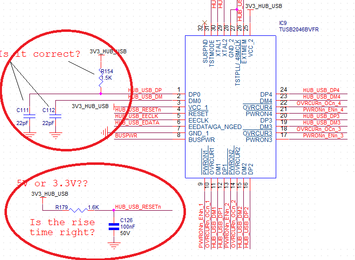
    2. Is the reset circuit reported hereinafter right? 3.3V is correct? The time constant set by R179 and C126 is right?

    3. Are the R154, C111 and C112 correct?

    Thank you and BR.

    Ste

  • Hi Stefano,

    The important thing for unused ports is that they look like a single-ended zero to the port receiver.  Our recommended way to do this is to tie the DP and DM together and pull them low, but pulling them low individually works as well.

    Reset should be pulled to 3.3V.  I would consider increasing the resistor on the RC circuit on the RESET pin.  The requirement in the datasheet is:  Generally, a reset with a pulse width between 100 μs and 1 ms is recommended after 3.3-V VCC reaches its 90%.  The 1.6K is on the low side.  I would try value closer to 10k to start.

    The caps and pullup are correct for the upstream port connection.  Are the series resistors also in the path?

    Regards,

    JMMN

  • Hi JMMN,

    hereafter some more question.

    1. You wrote: "The caps and pullup are correct for the upstream port connection.  Are the series resistors also in the path?"

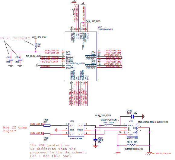
         In the path there are 22ohm resistors (R188, R189) as reported in the following picture. Is it right?

    2. What about the U24 (ESD protection: https://www.mouser.it/datasheet/2/389/usblc6-2-1852789.pdf )?

        It is different then the suggested one in the datasheet. I would prefer this. But the question is: is it the right one as well?

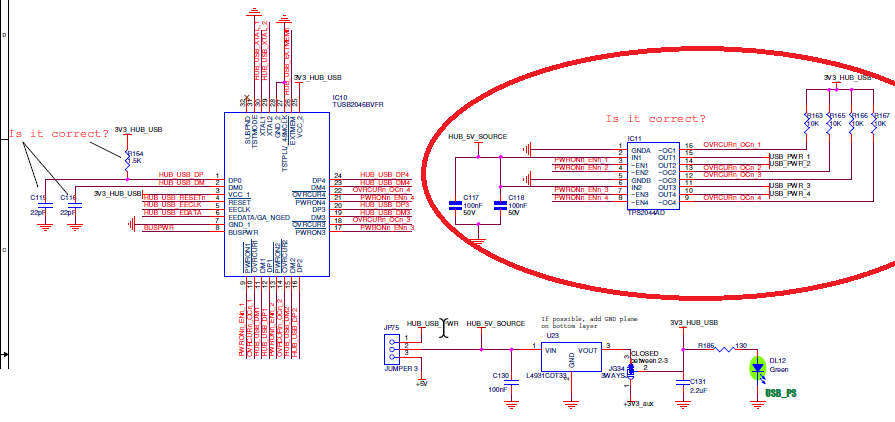
    3. What about the power management reported in the following picture. Is IC11 rightly connected?

    Thank you an BR.

    Ste

  • Hi Stefano,

    1. This looks good.

    2. Yes, ESD is rated for USB, should be fine.

    3. Power management looks ok too.

    Regards,

    JMMN