This thread has been locked.

If you have a related question, please click the "Ask a related question" button in the top right corner. The newly created question will be automatically linked to this question.

TPS25832-Q1: TPS25832-Q1 for client mode

Part Number: TPS25832-Q1
Other Parts Discussed in Thread: TUSB320

Hello,

Unfortunately, setting CTRL1 and CTRL2 lines to LOW is not working for client mode.
We have now a design and tried this to download our software to the processor. But the processor is not connecting to computer. By shorting DPM_OUT and DPM_IN pins with JP1 - JP4 it works.

It seems, TPS25832 disconnects the DPM_OUT from DPM_IN pins.

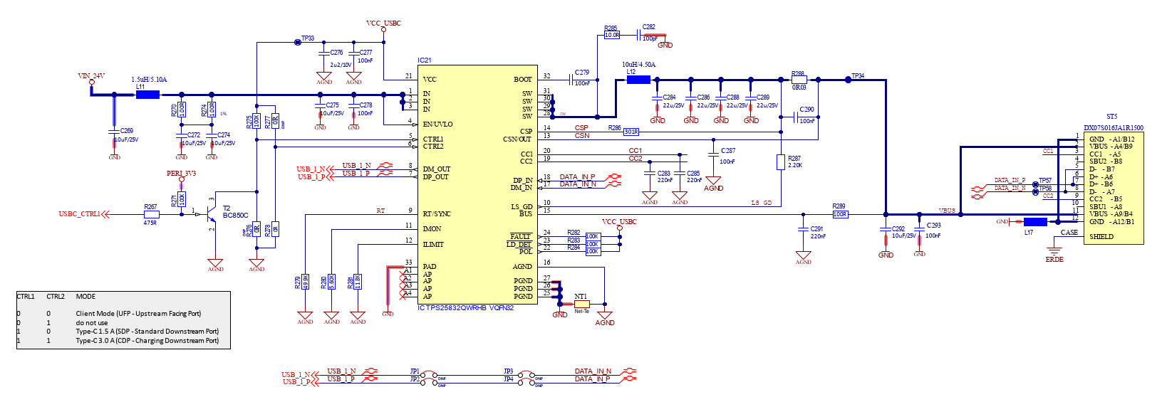
This is how we implemented the controller:

USB_CTRL1 line is connected to processor. When the processor is empty there is a 100k pull-down resistor. So the setting on CTRL1 and CTRL2 is LOW. 

I think, we have to use another USB-C controller for this purpose.

Can you recomend one?

Best regards,

Dani

  • Hi Daniel,

    When you set the client mode ,you should add the external FET to turn off the internal buck output (VCSN will always have 5V ouput , it need the FET turn off this voltage to VBUS) .

    Another, the R289 value should change from100ohm to 20Kohm. 

    I think you can first change the resistor value and second add the FET to debug. 

  • Hi Michael,

    Why should R289 be 20kohm?

    Datasheet says 100ohm without FET and 10ohm with FET.

    So in Buck Average Mode, the TPS provides the 5V all the time except when overvoltage is detected?

    I measure 0V at VBUS when nothing is attached to USB-C connector with CTRL1 = HIGH / CTRL2 = LOW and also with CTRL1 = LOW / CTRL2 = LOW.

    I thought the TPS is only providing 5V to VBUS if the correct device is connected with CC1/2 pins on the device side of the cable?

    Unfortunately I can't add the FET on my PCB now, this has to be done in the next revision of the Layout.

  • Hi Daniel,

    Sorry I misunderstand you use the TPS25830 for type A port client mode.

    So, you issue is the data switch  will no turn on when you set CTRL1 and CTRL2 to low. 

    To my understand in client mode the VBUS should keep low in VBUS for the TPS25830. If not the 5V power in your computer will conflict with the TPS25830 VBUS output. 

    To be aware, the TPS25830-Q1will detect whether BUS voltage have been discharge to 0V during startup. 

    When you plug the cable to the port the cable  may have 5V to TPS25830 BUS pin , that will cause the TPS can't start up and data switch can't  turn on.

    For this issue, I suggest you to change the 100ohm resistor to 20Kohm to block the 5V voltage charge up the BUS pin. 

  • Hi Michael,

    No as in the title, the schematic and the datasheet I posted, we use the TPS25832-Q1.

    I switched the resistor now to 20kohm.

    So with CTRL1 and CTRL2 LOW TPS25832 is not providing 5V (USB cable not attached at startup). This is correct and the behaviour I want, because we than plug an USB-Cable from PC to the TPS25832 and providing 5V from PC. This is for client mode and we dont use the 5V from PC.

    But in this case we need the datalines connected to the processor to download our software.

    But this don't happens.

    The other case when CTRL1 = HIGH and CTRL2 = LOW, we use to connect USB-Devices to the TPS25832. Then we need 5V provided by TPS25832.

    My plan is when booting the processor, the TPS25832 is set to client mode. And after bootet up, we switch to the USB-C mode by setting CTRL1 to high.

    Is this even possible to switch the CTRL1 line from High to Low when TPS25832 is powered and running?

    I tested the TPS25832 now also with an USB-device attached.

    In both cases (client mode and device mode) TPS25832 provides 5V to the BUS after attaching a device. So also in client mode, when an USB-device is connected the TPS25832 provides 5V. 

  • Hi Daniel,

    I think the issue is the  CC1 or CC2 pin may don't have  the Rd  when you plug in the C cable , the TPS25832 will not wave up untill the CC1/2 have the Rd attached. 

    When the device wave up the DP/M data switch will turn on and you can do the communication between PC and  832.

    You may notice that the 832 will always turn on the VSCN(5V) when Rd attached.  If you need block this 5V output , you should add the external FET to blocking. Actually, in the  client mode , the LS_GD pin will set low but  VSCN always have 5V. That's why I ask you to add the external FET in your schematic for the client mode application. But, you said the PC will don't have the 5V output to 832, the issue maybe 832 can't present as the UFP, it can't turn on the PC type C port, then the PC type C port can't be wake up for communication.

  • Hi Michael,

    Thats right, when using 832 in client mode, we have a USB2.0 type A to USB-C cable. There is no Rd in that cables.

    We do not use a Type-C to Type-C cable for downloading our software from PC.

    Now I understand the behaviour. I thought in client mode there is no need for Rd. So I think we change to TUSB320 for the next revision to have a real DRP USB-C.

    Thanks a lot for help.