This thread has been locked.

If you have a related question, please click the "Ask a related question" button in the top right corner. The newly created question will be automatically linked to this question.

TPS65987DDJ: 20V configuration

Part Number: TPS65987DDJ
Other Parts Discussed in Thread: TPS65987D,

Hi Adam,

Kindly find earlier thread link for customer requirement for which we have exchanged queries & response for TPS65987D - 100watt configuration.

Now customer has received the boards & facing issues with 20V configuration. They are able to get the default configuration setting till 15V but not able to do for 20V.

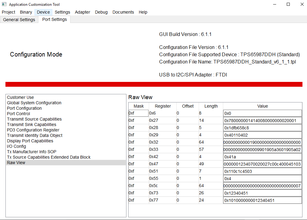
How to configure for 20V PD possibly without external Flash memory?

If Flash memory then how to do the same? How to write the flash?

Pls. help as customer is in hurry to resolve the issue.

Mitesh

  • Hello,

    In the thread title, you list the TPS65987DDJ  but in your post, you list the TPS65987D. Would you be able to clarify which device you are using and make sure that you are using the correct tools?

    If you would like to support 20V/5A, you will need to use an external flash.

    You will need to use some type of programmer to update the flash image. You update the configuration of the PD controller using the application configuration tool (https://training.ti.com/tps6598x-application-customization-gui-tool-basic-introduction), you produce a binary image from this updated project file, and then you flash this updated binary to the external EEPROM. 

  • Hi Adam,

    Thanks for your suggestions & as you suggested to program the external flash, after that customer is able to resolve the issue & able to detect the 20V charger.

    Sorry for the confusion about correct device number, it is TPS65987DDJ.

    Now they want only 20V/3A or 20V/5A or 15V/4A or above chargers only wants to work with their HW, basically 60 watt chargers only should be detected & rest of the charger should not allow the power up their rest of the HW. Is there any programming register which can pass only 20V/3A-5A, 15V/4A-5A chargers.

    Mitesh

  • Hi Adam,

    Pls. Help on previous post. Also find attached set of registers which customer wants to write and they are not to.

    blob:null/08035898-dcd6-4ad2-afd3-2c37ddca6fea

    Mitesh

  • Hello Mitesh,

    As defined by the USB Type-C PD spec, 5V must first be negotiated on VBUS before transitioning to a high voltage contract like the ones you outlined above. By this definition, we supply 5V to PPHV before we know the charger capabilities.

    If your customer does not want this type of behavior and they have some type of embedded controller connected to our PD controller via I2C, then they can implement the 'SRDY' 4cc command as explained in the host interface technical reference manual. What this command does is that the PD controller still negotiates a contract with the connected charger, but does not close the internal power paths until it receives this command from the embedded controller. The embedded controller would know that a 60W charger is connected by register 0x34 (active contract VDO)

    If you customer does not have an embedded controller connected to the PD controller that is able to issue this command, then it is not possible to close the internal power path only when a charger >60W has been connected

  • Thanks Adam,

    There are few registers they are not able to write or modify, can you guide us for the same?

    Here is the attachment.

    Mitesh

  • Hello,

    Would you be able to elaborate more? Which registers are they unable to modify?

    Also are they modifying these registers using the GUI or their embedded controller?

    If they are using the embedded controller, would you be able to share a I2C capture of their communication? 

  • Hello Adam;

    Myself Chirag Solanki; working on this project. Mitesh Patel (TI) is supporting us for the USB PD configuration issues and requirements for this design.

    Regarding your query; we would like to write the few registers such as 0x37 Auto Negotiate Sink; which is not available in GUI list of registers as shown in above image. We want to update this register for the for few parameters such that ANSinkMinRequiredPower or AutoComputeSinkMinPower field while flashing the file into SPI Flash. So we would like to know how can we update the registers which are not part of GUI; that is accessed during the Power On event ?

    We have CPU that is connected to USB PD over I2C; but that will be ON when >15V is available from PD Source.

    Apart from this; there is below requirement:

    - Is it possible to connect the AC Adapter with USB Type C Connector that can support 20V Output ? This can be simple AC adapter but with USB TYPE C connector ? if yes; Is there any register settings available for this ?

    - Similarly what if I connect the Battery Power Bank that has USB Type C Connection?

    - Register 0x33 - TX Sink Capabilities Register - can we configure this register for Fixed Supply of 20V @ 3A ? Which field need to be set? By setting this field; whether USB PD will allow the lower voltage/current USB PD source to connect or will reject?

    Please let me know if any further information need to provide your suggestions on above points.

    Regards,

    Chirag

  • Hello Adam,

    Could you please update for the query response?

    Also; there is one more point need your suggestion:

    It is possible to select the Higher Voltage of 20V from PD source thru register configuration. We would like to know is there any register setting whereby we can also specify the minimum current required from the PD Source? For example; requirement is 20V @ 3A from PD Sink side. So the PD sink should not negotiate to 20V unless the PD source has 20V @3A capacity; otherwise it would negotiate to 5V only. Thus; we want to make sure that only 20V@3A Source can negotiate to 20V; or else it would be at 5V.

    Regards,
    Chirag

  • Hello,

    You are currently using the standard project template. If you wish to acces the auto negotiate sink register, you must use the advanced GUI template. This is done by clicking Project -> New Project and selecting one of the advanced templates based on your requirements

    Here are the answers to your questions:

    1. As long as the Type-C adapter is capable of communicating via Type-C PD messaging, then it will negotiate a contract by default and the PD controller will handle it as any other Type-C PD source

    2. This depends on what you want your device to do. It will either act as a source charging the power bank or act as a sink drawing power from the power bank.

    3. You cannot configure a device to only be able to sink 20V. You must first negotiate a 5V sink contract and can then transition to a high voltage contract such as 20V

    4. Yes, in the auto negotiate sink register, their is a minimum power requirement register. You can enable this field so that the system requires a minimum of 60W

  • Adam,

    Thanks for providing your inputs.

    Customer's team is able to detect voltage to qualify the adapter as PD source & now they are able to detect only 20V or 5V PD source depending on negotiation.

    Only issue is w.r.t. current, they are not able to detect 60 watt and above PD source. If you can point which exact registers need to program may be current or power registers?

    Mitesh


  • Hello,

    The current capabilities of the charger can be determine by the active contract PDO register. I've also included how to decode this register based on the Type-C spec