This thread has been locked.

If you have a related question, please click the "Ask a related question" button in the top right corner. The newly created question will be automatically linked to this question.

HD3SS213: questions about datasheet

Part Number: HD3SS213

Dear expert,

My customer has some questions regarding HD3SS213-TI and would like to consult with TI, thank you! !
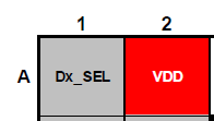
1. Regarding the pin description, it indicates that only Pin J4 is the VDD pin, but Pin A2 also shows VDD in the Ball map, which one is right?

  2. DP interface, under what scenario will DDC interface be used?
3. If only the AUX interface is used and the DDC interface is not used, how to deal with the pins corresponding to the DDC?
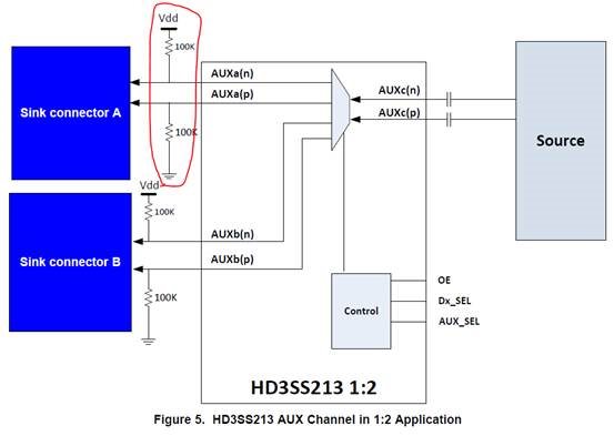
4. Why is the in-place detection circuit on AUX placed close to the Sink end? Can it be placed on the Source side?

  • Hi,

    1. Please refer to the latest HD3SS213 datasheet, SLAS901B –SEPTEMBER 2013–REVISED DECEMBER 2016 which shows both A2 and J4 are VDD pins. 

    2. DDC is not used for a DP-only application, only AUX bus will be used.

    3. Unused DDC pins can be left floating on both sides of the HD3SS213.

    4. No, 100k pullup/pulldown has to be on the sink per the DP spec requirement.

    Thanks

    David