This thread has been locked.

If you have a related question, please click the "Ask a related question" button in the top right corner. The newly created question will be automatically linked to this question.

DS90UB914A-Q1: Couldn't Communicate to DS90UB913A-Q1

Part Number: DS90UB914A-Q1
Other Parts Discussed in Thread: USB2ANY, ALP

Hi Experts,

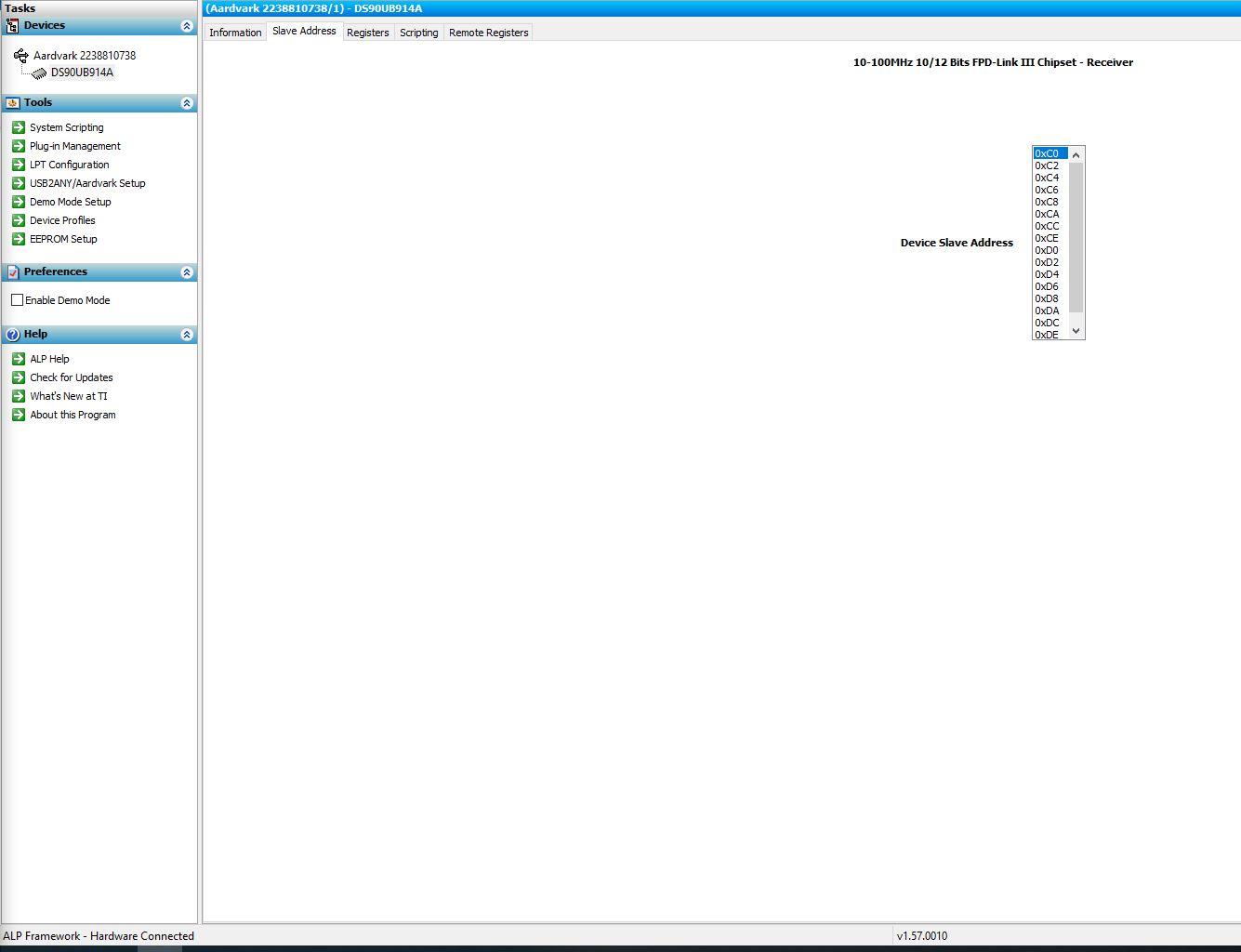
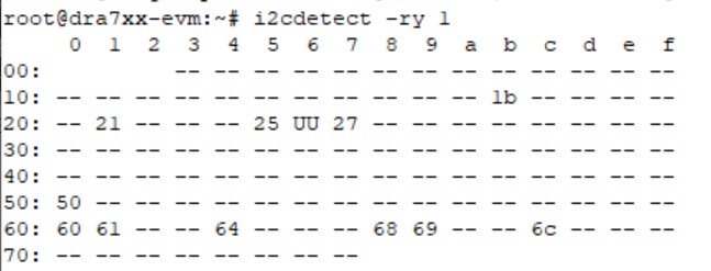
I am trying to connect OV10635 camera to the TDA2x5777EVM board, in the process I am supposed to use SAT0089-SAT0088 components. After connecting the multi-des board to the EVM, I am able to find the following I2C devices:

1)    6 – Deserializers (0x60, 0x61, 0x64, 0x68, 0x69, 0x6c)

2)    3 – GPIO expander chip (0x27, 0x21, 0x25)

3)    1 more device (0x50)

I2C Devices

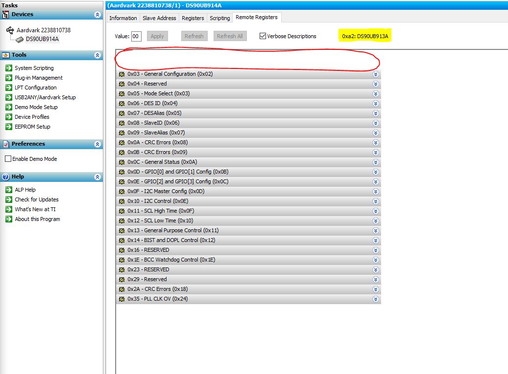
After setting the pass through all bit (0x21 to 0x97) and Serializer Alias (0x07 to 0xb0), the Deserializer register reads as below

DES Register Values

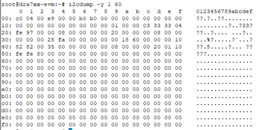
After doing these setting, I am not able to see the Serializer 913 in the I2C bus.

With the help of I2C expander, I also conducted the BIST to check the Serializer communication. Expander setting are as follows:

#i2cset -y 1 0x27 0x00 0x0f

#i2cset -y 1 0x27 0x12 0xf0         -> enable bist

#i2cset -y 1 0x27 0x12 0xe0         -> disable bist

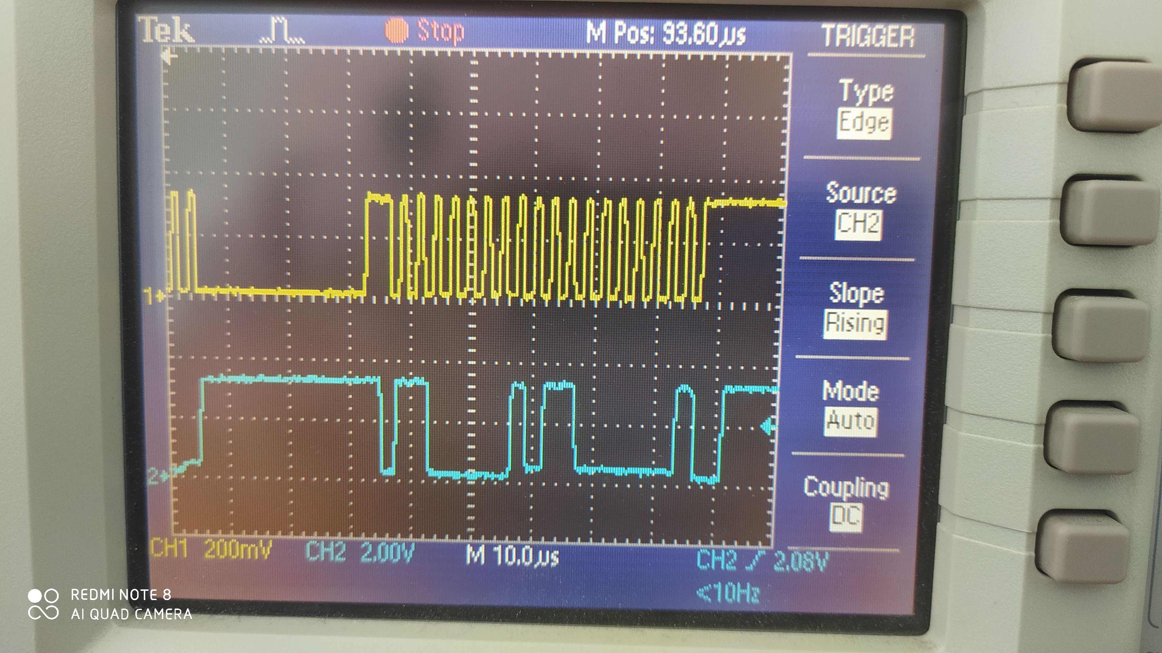
Below are the BIST results.

BIST

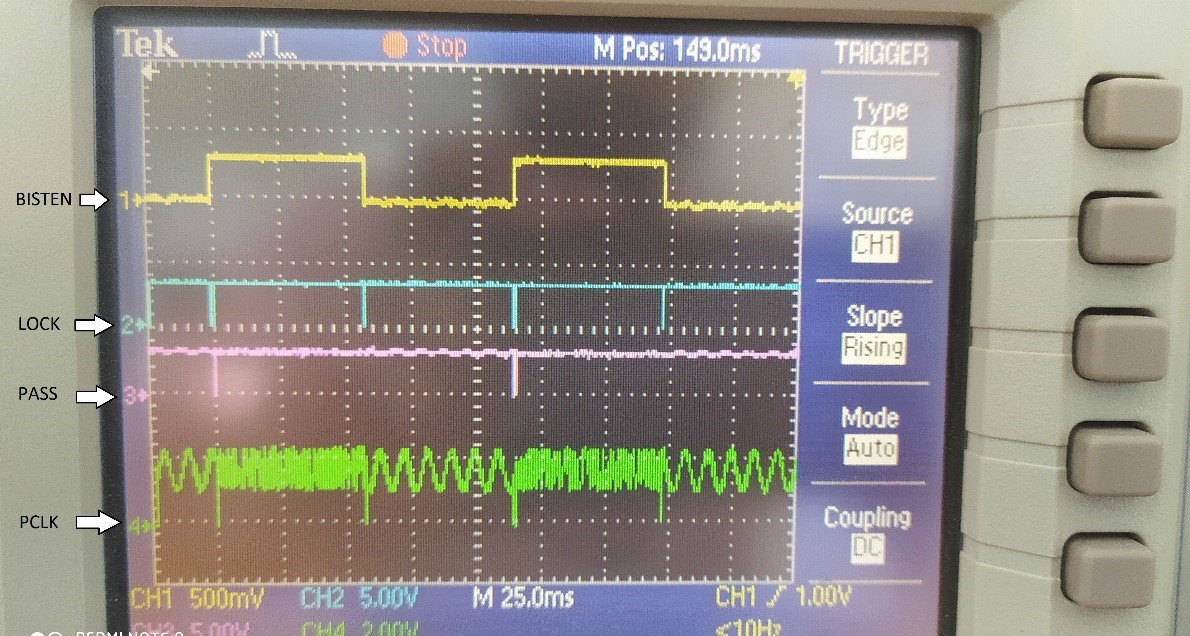
BIST results are pass, but I couldn't see serializer.

Captured the power-up sequence of the deserializer to check the characteristics, and I found those are as per datasheet

Power Up Sequence

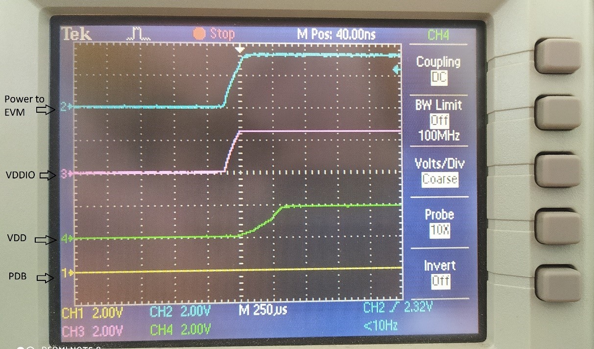
Please help me to establish a communication with the Serializer and in turn to the camera.

  • Hello Subramaniyan,

    Try setting the I2C Remote Write Auto Acknowledge (Register 0x03 bit 4) of the 913A. If that doesn’t work, try setting I2C PassThrough All (bit 3 of register 0x03) as well.

    Regards,

    Carrie

  • Hi Carrie,

    I am not able to see 913A in the I2C bus. I don't know the device address to read or write the register values. Is there any other way to set the registers of SAT0088?

    Regards,

    Subramaniyan

  • Hello Subramaniyan,

    You should be able to access the 913 registers remotely through the deserializer. The I2C address can be read from the deserializer. From your register dump, the 8-bit serial alias is 0xB0 after you configure it. Try i2c get 0xB0 0x00, and if you get the serial address back, you have established i2c access with the 913 and can change the register values.

    Regards,

    Carrie

  • Dear Carrie,

    There is a forward channel communication from SER -> DES, so the SER ID register(0x06) in 914 is updated with 0xb0 value. After setting the alias address in the register 0x07 with 0xb0, if I try to read the value from the 913 SER (7 bit address) using below utility

    I get this error "i2cget: read failed: Remote I/O error". 

    While measuring the I2C signals during the Serializer read, I am not getting the acknowledgement signal from serializer.


    Below is the I2C signal for Serializer read: (No Acknowledgement)

    SER I2C Read

    Below is the I2C signal for Deserializer read: (Acknowledgement is coming, image 2 shows read value from 914 DES register)

    I2C Read First Part

    DES I2C Read Part 2

    I hope, I am meaningful.

    Due to some reasons, I am not able to read the 913 SER registers. Please let me know how to communicate to the SER.

    Regards,

    Subramniyan

  • Hello Subramaniyan,

    On the 914, try enabling the Auto Ack bit (bit 2) and the I2C pass through bit (bit 3) of the General Configuration 1 register (0x03). Also, try setting the serial alias to a 7-bit value between 0x09 and 0x17. Then try to access the serializer.

    Once you have configured this, please send another register dump for the 914.

    Regards,

    Carrie

  • Hi Carrie,

    I2C pass through bit of General Config register 1 (0x03) is set by default, I have set the Auto Ack bit of GC1 register (0x03). 

    Also I have set the Slave ID registers and Slave Alias registers along with SER ID registers and SER alias registers.

    DES_Reg_Values

    But still I couldn't access the Serializer.

  • Hello Subramanyan,

    I am looking into this and will get back to you tomorrow.

    Regards,

    Carrie

  • Good afternoon,

    Try disabling “I2C Pass-Through All” bit (0x21[7]) on the 914A and then use 7-bit addressing to access 913A registers.

    Regards,

    Carrie

  • Hi Carrie,

    I have disabled "I2C Pass though all"bit and tried with SER alias 7-bit address as 0x58 and 0x59. Still I couldn't access 913A registers. PFB the register values of 914

    DES Register Values

    With Regards,

    Subramaniyan

  • Hello Subramaniyan,

    Read the default loaded alias from register 0x07. Instead of setting it to 0xB0, try using this value to access the serializer.

    Regards,

    Carrie

  • Hi Carrie,

    The default value of the serializer alias register(0x07) is 0x00, with serializer 913A connected to deserializer 914A. Hereby I attach the text file with default values of all registers read from 914A. I was setting the value of 0xb0 and 0xb2 after going through the I2C over DS90UB913/4 FPD-Link III with Bidirectional Control Channel (snla222) application report.

    Note:

    In datasheet also against the 0x07 register, it is mentioned that value of 0x00 would disable the communication to the remote serializer.  

    Thanks,

    Subramaniyan

    Value at Register  0x0  in device  0x60 is:
    0xc0
    Value at Register  0x1  in device  0x60 is:
    0x04
    Value at Register  0x2  in device  0x60 is:
    0x00
    Value at Register  0x3  in device  0x60 is:
    0xe9
    Value at Register  0x4  in device  0x60 is:
    0x00
    Value at Register  0x5  in device  0x60 is:
    0x00
    Value at Register  0x6  in device  0x60 is:
    0xb0
    Value at Register  0x7  in device  0x60 is:
    0x00
    Value at Register  0x8  in device  0x60 is:
    0x00
    Value at Register  0x9  in device  0x60 is:
    0x00
    Value at Register  0xa  in device  0x60 is:
    0x00
    Value at Register  0xb  in device  0x60 is:
    0x00
    Value at Register  0xc  in device  0x60 is:
    0x00
    Value at Register  0xd  in device  0x60 is:
    0x00
    Value at Register  0xe  in device  0x60 is:
    0x00
    Value at Register  0xf  in device  0x60 is:
    0x00
    Value at Register  0x10  in device  0x60 is:
    0x00
    Value at Register  0x11  in device  0x60 is:
    0x00
    Value at Register  0x12  in device  0x60 is:
    0x00
    Value at Register  0x13  in device  0x60 is:
    0x00
    Value at Register  0x14  in device  0x60 is:
    0x00
    Value at Register  0x15  in device  0x60 is:
    0x00
    Value at Register  0x16  in device  0x60 is:
    0x00
    Value at Register  0x17  in device  0x60 is:
    0x00
    Value at Register  0x18  in device  0x60 is:
    0x00
    Value at Register  0x19  in device  0x60 is:
    0x01
    Value at Register  0x1a  in device  0x60 is:
    0x00
    Value at Register  0x1b  in device  0x60 is:
    0x00
    Value at Register  0x1c  in device  0x60 is:
    0x03
    Value at Register  0x1d  in device  0x60 is:
    0x33
    Value at Register  0x1e  in device  0x60 is:
    0x33
    Value at Register  0x1f  in device  0x60 is:
    0x04
    Value at Register  0x20  in device  0x60 is:
    0xfe
    Value at Register  0x21  in device  0x60 is:
    0x17
    Value at Register  0x22  in device  0x60 is:
    0x00
    Value at Register  0x23  in device  0x60 is:
    0x00
    Value at Register  0x24  in device  0x60 is:
    0x08
    Value at Register  0x25  in device  0x60 is:
    0x00
    Value at Register  0x26  in device  0x60 is:
    0x00
    Value at Register  0x27  in device  0x60 is:
    0x00
    Value at Register  0x28  in device  0x60 is:
    0x00
    Value at Register  0x29  in device  0x60 is:
    0x20
    Value at Register  0x2a  in device  0x60 is:
    0x00
    Value at Register  0x2b  in device  0x60 is:
    0x00
    Value at Register  0x2c  in device  0x60 is:
    0x00
    Value at Register  0x2d  in device  0x60 is:
    0x08
    Value at Register  0x2e  in device  0x60 is:
    0x00
    Value at Register  0x2f  in device  0x60 is:
    0x00
    Value at Register  0x30  in device  0x60 is:
    0x00
    Value at Register  0x31  in device  0x60 is:
    0x00
    Value at Register  0x32  in device  0x60 is:
    0x00
    Value at Register  0x33  in device  0x60 is:
    0x25
    Value at Register  0x34  in device  0x60 is:
    0xfa
    Value at Register  0x35  in device  0x60 is:
    0x00
    Value at Register  0x36  in device  0x60 is:
    0x00
    Value at Register  0x37  in device  0x60 is:
    0x00
    Value at Register  0x38  in device  0x60 is:
    0x00
    Value at Register  0x39  in device  0x60 is:
    0x00
    Value at Register  0x3a  in device  0x60 is:
    0x18
    Value at Register  0x3b  in device  0x60 is:
    0x60
    Value at Register  0x3c  in device  0x60 is:
    0x00
    Value at Register  0x3d  in device  0x60 is:
    0x00
    Value at Register  0x3e  in device  0x60 is:
    0x00
    Value at Register  0x3f  in device  0x60 is:
    0x10
    Value at Register  0x40  in device  0x60 is:
    0x82
    Value at Register  0x41  in device  0x60 is:
    0x82
    Value at Register  0x42  in device  0x60 is:
    0x00
    Value at Register  0x43  in device  0x60 is:
    0x35
    Value at Register  0x44  in device  0x60 is:
    0x00
    Value at Register  0x45  in device  0x60 is:
    0x00
    Value at Register  0x46  in device  0x60 is:
    0x00
    Value at Register  0x47  in device  0x60 is:
    0x00
    Value at Register  0x48  in device  0x60 is:
    0x00
    Value at Register  0x49  in device  0x60 is:
    0x08
    Value at Register  0x4a  in device  0x60 is:
    0x00
    Value at Register  0x4b  in device  0x60 is:
    0x00
    Value at Register  0x4c  in device  0x60 is:
    0x00
    Value at Register  0x4d  in device  0x60 is:
    0x20
    Value at Register  0x4e  in device  0x60 is:
    0x00


  • Hello,

    Please send the serial address and serial alias read from each deserializer after device configuration.

    Regards,

    Carrie

  • Hi Carrie,

    As at present we are concentrating on the Serializer, I haven't set the slave address registers and slave alias registers. I have set only the General Config 1 register (0x03) for acknowledgement, and  Serializer Alias register (0x07). 

    SAT0089 board has 6 FPD ports, I have connected 4 Serializers against the DES 0x60, 0x64, 0x68 and 0x6c. DES 0x61 and 0x69 are not connected to SER. Below images show the register values, default against modified. Modified Values are boxed in red color.

    914A - 0x60:

    DES_1_0x60

    914A - 0x64:

    DES_2_0x64

    914A - 0x68:

    DES_2_0x68

    914A - 0x6c:

    DES_2_0x6c

    Please let me know, if I have to furnish some more details.

    Regards,

    Subramaniyan

  • Hello Subramaniyan,

    Based on the register dumps of the deserializers it looks like the serializers are properly locked and communication should be available through the link. If you are still not able to access the serializer then the issue may be related to the SW stack of TDA. Have you contacted Spectrum Digital regarding this issue? Because they may have more familiarity with this system and SW to bring the board up

    Best Regards,

    Casey 

  • Hi Casey,

    Still I couldn't see the serializer in I2C bus. I am able to see the deserializer in the I2C bus but not the serializer, kindly enlight me how the SW stack may affect only the serializer.

    If register dumps of 914A are okay, can you please share some I2C command that should allow me to communicate to the SER 913A and modify SER registers. 

    I have initially wrote to Spectrum Digital and the response is as follows:

    Query_SD

    They have asked contact TI for help about SAT0088/SAT0089. A detailed mail conversion is attached to here.

    Query_SpectrumDigital.htm

    Note:

    If required, I can share some more results and electrical signals.

    Regards,

    Subramaniyan

  • Subramaniyan,

    The register dumps that you provide indicate that the SER/DES are properly locked and the I2C aliasing configuration is correct. So it seems that the only remaining issue would be related to the processor SW, otherwise from the SERDES perspective we don't see any reason why the SER should not be accessible. Do you have access to a USB2ANY or Aardvark module that can be connected directly to the I2C bus to bypass the system SW and run isolated testing of just the FPD-Link devices?

    Best Regards,

    Casey 

  • Hi Casey,

    Here are some queries to get more clarity:

    1) Do I need to modify I2C frequency from 400K to 100KHz, will that be of help? 

    2) Is locking of SER to DES happens through I2C line?

    3) Is there any place or points available in the SAT0088 board (913A) to measure the I2C signals? As till now all our signal measurements are at SAT0089 board (914A).

    4) Do I need to post a query in Processor forum to get clarity about SW? Or in any other forum?

    We have ordered the USB2ANY device for debugging and waiting for its arrival.

    I highly appreciate the regular responses and foresee the same.

    Thanks and Regards,

    Subramaniyan

  • Hello Subramaniyan,

    I am looking into this and will get back to you tomorrow.

    Regards,

    Carrie

  • Hello Subramaniyan,

    1)      The device is validated to run at an I2C frequency of 400 KHz, so that shouldn’t make a difference within the chip itself. You can try it.

    2)      LOCK indicated that the deserializer PLL is locked onto the incoming clock signal over the link. It is not something that is communicated from the serializer to the deserializer via I2C. You can look at section 9.4.4 of the 914A datasheet for more details.

    3)      Do you have an EVM for the 913A?

    4)      Yes, I would check with the processor manufacturer to get clarification on their software.

    Regards,

    Carrie

  • Hi Casey/Carrie,

    I have tried with ALP, still I couldn't read or write 913A registers. Kindly see the below steps which I have followed and let me know anything am missing with:

    1) Connected the hardware with Aardvark adapter then to the Win 10 machine through USB. I have validated status bar and it read "ALP Framework - Hardware Connected"

    2) Selected "DS90UB914A" from the defined ALP Devices under the Aardvark setup

    3) Then selected the first deserializer (0xC0) from the slave address list 

    Slave Address List

    Some observations in the ALP tool:

    1) "Information" tab is empty and doesn't have any detail on it

    2)  In the "Registers" tab, I am able to see and modify the register values. Have modified the SER Alias Register to 0xA2 value. Register dump is as follows:

    Register Display - ALP Nano 1 - DS90UB914A, Connector 1

    Register Data Name
    0x0000 0xC0 I2C Device ID
    0x0001 0x04 Reset
    0x0002 0x00 General Configuration 0
    0x0003 0xE9 General Configuration 1
    0x0004 0x00 EQ Feature Control 1
    0x0005 0x00 EQ Feature Control 2
    0x0006 0xB0 SER ID
    0x0007 0xA2 SERAlias
    0x0008 0x00 SlaveID[0]
    0x0009 0x00 SlaveID[1]
    0x000A 0x00 SlaveID[2]
    0x000B 0x00 SlaveID[3]
    0x000C 0x00 SlaveID[4]
    0x000D 0x00 SlaveID[5]
    0x000E 0x00 SlaveID[6]
    0x000F 0x00 SlaveID[7]
    0x0010 0x00 SlaveAlias[0]
    0x0011 0x00 SlaveAlias[1]
    0x0012 0x00 SlaveAlias[2]
    0x0013 0x00 SlaveAlias[3]
    0x0014 0x00 SlaveAlias[4]
    0x0015 0x00 SlaveAlias[5]
    0x0016 0x00 SlaveAlias[6]
    0x0017 0x00 SlaveAlias[7]
    0x0018 0x00 CRC Errors THRESHOLD
    0x0019 0x01 CRC Errors THRESHOLD
    0x001A 0x00 CRC Errors
    0x001B 0x00 CRC Errors
    0x001C 0x03 General Status
    0x001D 0x33 GPIO[1] and GPIO[0] Config
    0x001E 0x33 GPIO[3] and GPIO[2] Config
    0x001F 0x04 Mode and OSS Select
    0x0020 0xFE BCC Watchdog Control
    0x0021 0x17 I2C Control 1
    0x0022 0x00 I2C Control 2
    0x0023 0x00 General Purpose Control
    0x0024 0x08 BIST Control
    0x0025 0x00 BIST ERROR COUNT
    0x003C 0x00 OSC OUT DIVIDER SEL
    0x003F 0x10 CML OUTPUT ENABLE
    0x0040 0x82 SCL High Time
    0x0041 0x82 SCL Low Time
    0x0042 0x00 CRC Force Error
    0x004C 0x00 SEL Register
    0x004D 0x20 AEQ Test Mode Select
    0x004E 0x07 EQ Value

    General Status Register 0x1C, shows the detect and lock condition of SER to DES

    SER Lock Condition

    3) In "Remote Registers" tab, I can see the Alias address and the SER name at the opening pane. But I couldn't see any of the SER register values. On trying to read the register using arrow button, the name vanishes as shown in the below image

    SER Remote Registers

    Kindly help me to solve the issue and connect to the SER and Slave.

    Thanks & Regards,

    Subramaniyan 

  • Hello Subramaniyan,

    I am looking into this and will get back to you tomorrow.

    Best regards,

    Carrie

  • Hello,

    Are you able to try running ALP with a “USB2ANY” module instead of Aardvark? 

    https://www.ti.com/tool/USB2ANY

    Regards,

    Carrie

  • Hi Carrie,

          We doesn't have "USB2ANY" device. From my understanding Aardvark Adapter and USB2ANY can be used with ALP software, as there is a Tool option named "USB2ANY / Aardvark Setup". We have procured Aardvark considering its flexibility to use with Linux. Kindly help me to solve the issue with Aardvark Adapter.

    Thanks & Regards,

    Subramaniyan

  • Hello Subramaniyan,

    Have you connected the Aadrvark I2C bus to the I2C bus of your board? That is the first step and then you can connect the ALP GUI with the Aardvark 

    Best Regards,

    Casey 

  • Hi Casey,

    Yeah, I have connected the I2C bus properly. In the second previous reply I have shared some screenshots of ALP tool, where I could read and write the 914A registers. But when I try to see the remote registers, which of 913A the values are blank. I couldn't read anything.

    Regards,

    Subramaniyan

  • Hi Subramaniyan, 

    Perhaps we can have a live discussion to see what's happening. Can you please email me s-cheung@ti.com and I we can set up a time to debug? 

    Thanks, 
    Sally 

  • Final resolution: The mode pin on the 914A was not configured properly, so it caused the wrong mode strapping which caused i2c issues. 

  • Thanks Sally,

    Along with the MODE setting, I also have to reset the DES by configuring the IO expander. After these two steps I am able to communicate between DES & SER.

    After resetting the DES, the mode gets effective and by setting the ALIAS address I could communicate.

    Thanks and Regards,

    Subramaniyan