This thread has been locked.

If you have a related question, please click the "Ask a related question" button in the top right corner. The newly created question will be automatically linked to this question.

DP83867IR: PHY_ID strap configuration

Part Number: DP83867IR
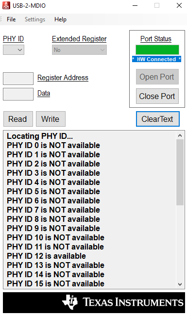
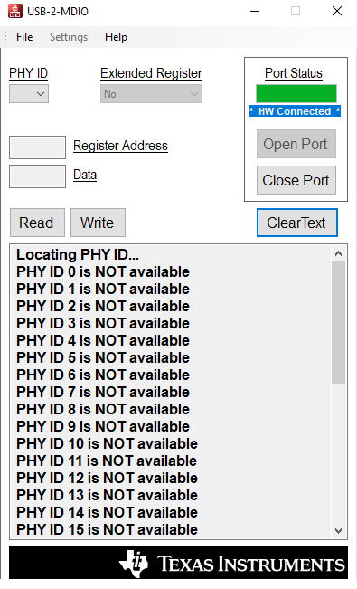
Other Parts Discussed in Thread: USB-2-MDIO

On TI DP83867IR data sheet (SNLS484F-FEB 2015-revised Dec.2019) page 47 Table 4. ( 4-Level Strap Resistor Ratios), it states that Rhi = 2.49K, Rlo = Open for Mode 4. On Page 53 Figure 28, RX_D4 is tied to GND, and description about this pin resistor configuration states RX_D4= Strap Mode 4. The question is that RX-D4 should be pulled to VDDID instead of connecting it to GND  in Figure 28, or I interpreted it wrong?

Please advise.

Thanks,

Jimmy

  • Hi Jimmy,

    Yes you are correct. Rx_D4's pull up of 2.49K should be VDDIO for Mode 4.

    --

    Regards,

    Vikram

  • Hi Vikram,

    Thanks. Your answer helps my understanding of PHY_ID strap configuration for DP83867IR PHY transceiver.

     I have a question relating PHY_ID strap configuration. We have a board using DP83867IRRGZ device, and its RX_D0 pin 33 is connected to GND through a 1K resister, RX_D2 pin 35 is connected to VDDIO through 1K resistor. Once power up, its PHY_ID = 0x0C, and the ethernet communication of the board with a link partner PC works. However, the ethernet communication does not work once we removed two 1K resistors from RX_D0 and RX_D2 pins while its PHY_ID = 0X00, which is matched with device spec of Table 4 on data sheet page 47.

    The question is that under the condition of PHY_ID is chosen to 0x00 (the default PHY_ID), why the ethernet does not work. Could you give us a hint?

    Thanks,

    Jimmy

  • Hi Vikram,

    Have not got your response to my last question. Do you think default PHY_ID can be used for ethernet communication?

    I have one more question about PHY_ID. We have two similar designs: one uses DP83867IRPAP 64-pin package, and the other uses DP83867IRRGZ 48-pin package. Both designs use same resistor strap configuration. In both designs, RX_D0 pin is connected to GND through a 1K resister, and RX_D2 pin is connected to VDDIO through 1K resistor. Once power up, the expected PHY_ID should be 0x0C. 

    We use TI Launch PAD and USB-2-MDIO tool kit to read PHY-ID once the board is powered up. The 64-pin board PHY_ID is available at 12, while the 48-pin board has no available PHY_ID, as shown in following screen shots:

    By the way, the test condition is the same, and two designs' schematic are almost the same.

    Could you shed a light for us about what will have effect on PHY_ID value? How can we get available PHY ID value?

    Thanks,

    Jimmy

  • Hello Jimmy,

    Kindly share the schematics of both the package devices so that I can review the connections of phy id straps.

    Phy ID (addresss) should not interfere in ethernet communication in anyway unless you are writting some phy registers to enable the link-up. Only writting and reading of registers will require phy id.

    --

    Regards,

    Vikram

  • Hi Vikram,

    Please find the schematic in both designs below:

    1106.GigE 64pin and 48pin_schematic.pdf

    Regards,

    Jimmy

  • Hi Jimmy,

    Regarding 48pin's phy id not showing up :

    I noticed that 64 pin version has a reset scheme attached to the resetn pin and that is not there with 48pin version. May be the 25MHz oscillator is not stablizing before the power ramp is stable and this may make the phy go into unknown state. Can we trying toggling the resetn pin (when you see no phy id issue) and then try to poll phy id? If the problem is because of clock stability during power-up, applying resetn should resolve it.

    Regarding ethernet communication not working with phyid = 00 :

    1. Were you able to see phy id as 00 in usb to mdio tool in that case?

    2. Is the link-partner also DP83867 or some other?

    3. Can you please share the value of  registers <0x0000>, <0x0001>, <0x006E> and register<0x006F> during the issue case? It will give us the boot up and link-up state of the phy.

    4. Do you write any registers to the phy after power up?

    --

    Regards,

    Vikram

  • Hi Vikram,

    Our 48-pin design has reset circuit there. Do you think the reset circuit works?

    If we don't think 25MHz oscillator is stable at the time of power ramp up, the oscillator is stable at the reset button is pressed and released so the PHY-ID should be latched into PHY register. However, the PHY_ID is still not available

    With our 64-pin design, we can see PHY_ID =0x00 once we removed two resistors (R56 and R57) on RX_D0 and RX_D2. However ethernet communication does not work in that case. We don't know why. It should work, right?

    The link partner in the test setup is a PC and Putty terminal emulator is used

    Please find the 64-pin design PHY register damp file (the scanning PHY_ID =12):

    DP83867 register dump.txt file is open...
    Register 0000 is: 1140
    
    Register 0001 is: 796D
    
    Register 0002 is: 2000
    
    Register 0003 is: A231
    
    Register 0004 is: 01E1
    
    Register 0005 is: CDE1
    
    Register 0006 is: 006D
    
    Register 0007 is: 2001
    
    Register 0008 is: 4006
    
    Register 0009 is: 0300
    
    Register 000A is: 3800
    
    Register 000D is: 401F
    
    Register 000E is: 00A8
    
    Register 000F is: 3000
    
    Register 0010 is: 4040
    
    Register 0011 is: AE02
    
    Register 0012 is: 0000
    
    Register 0013 is: 0000
    
    Register 0014 is: 29C7
    
    Register 0015 is: 0000
    
    Register 0016 is: 0000
    
    Register 0017 is: 0040
    
    Register 0018 is: 6150
    
    Register 0019 is: 4444
    
    Register 001A is: 0002
    
    Register 001E is: 0002
    
    Register 001F is: 0000
    
    Register 0025 is: CDE1
    
    Register 002C is: 0000
    
    Register 002D is: 401F
    
    Register 002E is: 00A8
    
    Register 0031 is: 796D
    
    Register 0032 is: 2000
    
    Register 0033 is: A231
    
    Register 0043 is: A231
    
    Register 0053 is: A231
    
    Register 0055 is: CDE1
    
    Register 006E is: 00A8
    
    Register 006F is: 3000
    
    Register 0071 is: 796D
    
    Register 0072 is: 2000
    
    Register 007B is: 0000
    
    Register 007C is: 0000
    
    Register 0086 is: 006D
    
    Register 00C6 is: 006D
    
    Register 00E9 is: 0300
    
    Register 00FE is: 00A8
    
    Register 012C is: 0000
    
    Register 0134 is: 01E1
    
    Register 0135 is: CDE1
    
    Register 0136 is: 006D
    
    Register 0137 is: 2001
    
    Register 0138 is: 4006
    
    Register 0139 is: 0300
    
    Register 013A is: 3800
    
    Register 013B is: 0000
    
    Register 013C is: 0000
    
    Register 013D is: 401F
    
    Register 013E is: 00A8
    
    Register 013F is: 3000
    
    Register 0140 is: 1140
    
    Register 0141 is: 796D
    
    Register 0142 is: 2000
    
    Register 0143 is: A231
    
    Register 0144 is: 01E1
    
    Register 0145 is: CDE1
    
    Register 0146 is: 006D
    
    Register 0147 is: 2001
    
    Register 0148 is: 4006
    
    Register 0149 is: 0300
    
    Register 014A is: 3800
    
    Register 014B is: 0000
    
    Register 014C is: 0000
    
    Register 014D is: 401F
    
    Register 014E is: 00A8
    
    Register 014F is: 3000
    
    Register 0150 is: 1140
    
    Register 0151 is: 796D
    
    Register 0152 is: 2000
    
    Register 0153 is: A231
    
    Register 0154 is: 01E1
    
    Register 0155 is: CDE1
    
    Register 0156 is: 006D
    
    Register 0157 is: 2001
    
    Register 0158 is: 4006
    
    Register 0159 is: 0300
    
    Register 015A is: 3800
    
    Register 015B is: 0000
    
    Register 015C is: 0000
    
    Register 015D is: 401F
    
    Register 015E is: 00A8
    
    Register 015F is: 3000
    
    Register 0161 is: 796D
    
    Register 0170 is: 1140
    
    Register 0171 is: 796D
    
    Register 0172 is: 2000
    
    Register 0180 is: 1140
    
    Register 0190 is: 1140
    
    Register 0191 is: 796D
    
    Register 0192 is: 2000
    
    Register 0193 is: A231
    
    Register 0194 is: 01E1
    
    Register 0195 is: CDE1
    
    Register 0196 is: 006D
    
    Register 0197 is: 2001
    
    Register 0198 is: 4006
    
    Register 019A is: 3800
    
    Register 019B is: 0000
    
    Register 019C is: 0000
    
    Register 019D is: 401F
    
    Register 019E is: 00A8
    
    Register 019F is: 3000
    
    Register 01A0 is: 1140
    
    Register 01A1 is: 796D
    
    Register 01A2 is: 2000
    
    Register 01A3 is: A231
    
    Register 01A4 is: 01E1
    
    Register 01D5 is: CDE1
    
    End of file.
    

    We don't write any register to the PHY after the power up.

    To recap our questions, 1) on our 64-pin design, everything is OK, and ethernet communication works while PHY_ID=12. However it does not work once the PHY_ID is configured to 0x00 (remove two resistors on DX-D0 and DX_D2 signal line). Why? 2) Why PHY_ID is not available on our 48-pin design although the resistor strap config is the same as our 64-pin design?

    Jimmy

  • Hi Jimmy,

    Yes if reset is toggled after clock is stable then it should have nullified possible issue because of initial unstable clock.

    Regarding 64 pin issue :

    1. Kindly share the register dump for the issue case (as mentioned earlier). The sent log is showing that link is up. You may dump the register 3-4 times and send the log so that we can capture some dynamically changing registers.

    2. As Rx_d0 and Rx_d2 are going to some other SoC also, are we sure that other SoC is not sensing level on rx_d0/d2 and changing some phy configuration? Is it possible to disconnect these signals from SoC (0 ohms removal etc) and still check the link? We dont think that there is a link otherwise between phy id and link on copper side.

    Regarding 48 pin issue :

    1. Can we again try disconnecting these pins from SoC (as suggested above) and check if SoC connection is impacting the phy id being latched?

    --

    Regards,

    Vikram

  • Hi Vikram,

    Regarding 64-pin design:

    1. The register dump file is already shared with you in my last response. You just click the link and register value should be seen

    2. We removed two pull UP/DOWN resistors on PHY RX_d0 and RX_D2 signals and we could verify the PHY_ID is 0x00 by using TI USB-2-MDIO tool. However the ethernet communication to its lick partner PC no longer work. While we put those two resisters back to RX-D0 and RX_D2 lines, and we verify the PHY_ID=0x0C. The ethernet communication with its link partner works again. Does it means that the default PHY_ID (0x00) is not valid PHY_ID for ethernet communication? 

    Regarding to 48-pin design:

    1. We have not disconnecting those pins from SoC since those traces are in between the layers and it is very difficult to do the surgery.

    Thanks,

    Jimmy

  • Hello Jimmy,

    For 64pin design :

    I requested for register dump when there is an issue (that is with phy_id = 00). But according to your previous reply the register dump is of phy_id = 12 :

    Please find the 64-pin design PHY register damp file (the scanning PHY_ID =12): 7077.dump6.txt

    According to this register dump also register<0x0001>[2]=1; which indicates that link between phy and pc is up. 

    Also the values of registers 0x006E and 0x006F do not look correct. As these register addresses are greater than 1F, we need to use following extended register read procedure (kindly confirm if you have used it already) :

    1. write register<0x000D> = 0x001F,
    2. write register<0x000E> = address of register to be read.
    3. write register<0x000D> = 0x401F
    4. read register <0x000E> for value of the register.

    The value of register 0x006E and 0x006F will tell us that boot-up/strapped state of phy when you see the issue.

    Just to be sure, when you say that ethernet communication does not happen with phy_id = 00, I assume that you are checking the link up with the PC. Is there any other parameter you are checking as failure?

    For 48pin design :

    Can you also share the following :

    1. Do you see 25MHz clock on clkout pin?

    2. Do you see around ~1V on Rbias pin?

    These parameters will help us identifiy is the chip is powered up or not.

    I assume that you are using same launchpad to check phy-id for 64pin and 48 pin device and hence launchpad should not be a problem.

    --

    Regards,

    Vikram

  • Hi Vikram,

    Please find DP83867 64-pin register dump file as PHY_ID = 0x00.

    DP83867 register dump.txt file is open...
    Register 0000 is: 1140
    
    Register 0001 is: 796D
    
    Register 0002 is: 2000
    
    Register 0003 is: A231
    
    Register 0004 is: 01E1
    
    Register 0005 is: CDE1
    
    Register 0006 is: 006F
    
    Register 0007 is: 2001
    
    Register 0008 is: 5006
    
    Register 0009 is: 0300
    
    Register 000A is: 7800
    
    Register 000D is: 0000
    
    Register 000E is: 0000
    
    Register 000F is: 3000
    
    Register 0010 is: 5048
    
    Register 0011 is: BE02
    
    Register 0012 is: 0000
    
    Register 0013 is: 9CC0
    
    Register 0014 is: 29C7
    
    Register 0015 is: 0000
    
    Register 0016 is: 0000
    
    Register 0017 is: 0040
    
    Register 0018 is: 6150
    
    Register 0019 is: 4444
    
    Register 001A is: 0002
    
    Register 001E is: 0002
    
    Register 001F is: 0000
    
    Register 0025 is: CDE1
    
    Register 002C is: 0000
    
    Register 002D is: 0000
    
    Register 002E is: 0000
    
    Register 0031 is: 796D
    
    Register 0032 is: 2000
    
    Register 0033 is: A231
    
    Register 0043 is: A231
    
    Register 0053 is: A231
    
    Register 0055 is: CDE1
    
    Register 006E is: 0000
    
    Register 006F is: 3000
    
    Register 0071 is: 796D
    
    Register 0072 is: 2000
    
    Register 007B is: 0000
    
    Register 007C is: 0000
    
    Register 0086 is: 006D
    
    Register 00C6 is: 006D
    
    Register 00E9 is: 0300
    
    Register 00FE is: 0000
    
    Register 012C is: 0000
    
    Register 0134 is: 01E1
    
    Register 0135 is: CDE1
    
    Register 0136 is: 006D
    
    Register 0137 is: 2001
    
    Register 0138 is: 5006
    
    Register 0139 is: 0300
    
    Register 013A is: 7800
    
    Register 013B is: 0000
    
    Register 013C is: 0000
    
    Register 013D is: 0000
    
    Register 013E is: 0000
    
    Register 013F is: 3000
    
    Register 0140 is: 1140
    
    Register 0141 is: 796D
    
    Register 0142 is: 2000
    
    Register 0143 is: A231
    
    Register 0144 is: 01E1
    
    Register 0145 is: CDE1
    
    Register 0146 is: 006D
    
    Register 0147 is: 2001
    
    Register 0148 is: 5006
    
    Register 0149 is: 0300
    
    Register 014A is: 7800
    
    Register 014B is: 0000
    
    Register 014C is: 0000
    
    Register 014D is: 0000
    
    Register 014E is: 0000
    
    Register 014F is: 3000
    
    Register 0150 is: 1140
    
    Register 0151 is: 796D
    
    Register 0152 is: 2000
    
    Register 0153 is: A231
    
    Register 0154 is: 01E1
    
    Register 0155 is: CDE1
    
    Register 0156 is: 006D
    
    Register 0157 is: 2001
    
    Register 0158 is: 5006
    
    Register 0159 is: 0300
    
    Register 015A is: 7800
    
    Register 015B is: 0000
    
    Register 015C is: 0000
    
    Register 015D is: 0000
    
    Register 015E is: 0000
    
    Register 015F is: 3000
    
    Register 0161 is: 796D
    
    Register 0170 is: 1140
    
    Register 0171 is: 796D
    
    Register 0172 is: 2000
    
    Register 0180 is: 1140
    
    Register 0190 is: 1140
    
    Register 0191 is: 796D
    
    Register 0192 is: 2000
    
    Register 0193 is: A231
    
    Register 0194 is: 01E1
    
    Register 0195 is: CDE1
    
    Register 0196 is: 006D
    
    Register 0197 is: 2001
    
    Register 0198 is: 5006
    
    Register 019A is: 7800
    
    Register 019B is: 0000
    
    Register 019C is: 0000
    
    Register 019D is: 0000
    
    Register 019E is: 0000
    
    Register 019F is: 3000
    
    Register 01A0 is: 1140
    
    Register 01A1 is: 796D
    
    Register 01A2 is: 2000
    
    Register 01A3 is: A231
    
    Register 01A4 is: 01E1
    
    Register 01D5 is: CDE1
    
    End of file.
    

    For 48-pin design, we do see the 25MHz clock on clkout pin. Vbrias= 1.0017V,  Also we see the MDI signal using a scope:

    We do use same LaunchPAD kit for PHY register access for both 64-pin and 48-pin designs.

    Question here is why PHY_ID is not available in our 48-pin design. It should only relating to resistor strap configuration on RX_D0 and RX_D2.

    REgards,

    Jimmy 

  • Hello Jimmy,

    Regarding 64 pin package :

    Thanks for sharing the log for 64 pin device with phy id = 00. But :

    1. here also I see that phy is linked up with the PC (as .reg<0x0001>[2] = 1).

    2. as mentioned in the previous thread register values of 0x006E and 0x006F are not correct. (Was suggested procedure of register read followed?)

    So as I mentioned in previous thread, are you checking something other than link-up to declare communication failure? Do you think problem can be with the MAC/FPGA side as phy is showing link-up with the PC?

    Regarding 48 pin package :

    Looks like phy is powered up with clkout, rbias and MDI checks. Also you mentioned earlier that even by applying reset later in time (when input clock is stable) does not make phy id to appear. Only remaining thing that I can think of is that is there any difference in MDC/MDIO routing between 48 pin board and 64 pin device? Is there some other device connected to MDIO line which is holding the line to a low or high value? May be we can capture MDIO and MDC signals to see if they are toggling fine for the 48 pin device.

    --

    Regards,

    Vikram 

  • Hi Vikram,

    Regarding 64-pin design:

    * we performed tests on the same setup except for

    a) PHY_ID=0x0C (DX_R0 pull down, DX_D2 pull up with 1k resistors)

    b) PHY_ID = 0x00 ( removed both 1K resistors from the board, which it is at default PHY ID =0x00)

    For a) it works --  the board can talk to its ethernet link partner PC via Putty utility

          b) it does not work -- talk to PC failed.

    We don't know why

    Regarding 48-pin design:

    MDC/MDIO are connected to both MAC and LaunchPAD MDC/MDIO. But both MDC/MDIO signal are toggle, as shown in the scope:

    Above scope trace is recorded while USB-2-MDIO GUI scans PHY_ID.

    It is a puzzle of no PHY_ID value in 48-pin design.

    Regards,

    Jimmy

  • Hello Jimmy,

    Regarding 64 pin :

    As phy is linking up fine with the PC (as derived from register reads), I suspect that the problem is at the MAC/Fpga side and something changes there when we change the resistor settings.

    For further debug, you may refer to following application note and test "digital loopback" without anything connected on RJ45. This will help you identify if there is any problem on the MAC side.

    Regarding 48 pins :


    Thanks for sharing the waveforms. Looks like there is some toggling but we may need to look at the zoomed version to see the data. Can we get the zoomed in scope capture of MDC and MDIO for first 40 cycles of MDC clock when you read register 0x0001 giving phy_id = 00 through usb2mdio tool? This will cover one complete read cycle of register and will help us know how phy is reacting to read request.

    As MAC and PHY are connected together when you are accessing MDC, MDIO bus...so is it possible to power down MAC so that only effectively PHY is on the line.

    Yes it is puzzling to see that PHY is not responding to any phy address even when we have checked that PHY is powered up fine.

    --

    Regards,

    Vikram 

  • Hi Vikram,

    We have proved that our 48-pin board has valid PHY_ID using SMI bus tool developed by our SW team. The reason before no stable PHY_ID via TI LaunchPAD is there is another master on SMI bus, from MAC device. Now, only MAC device is used, and no TI LaunchPAD involved. so stable PHY_ID can be obtained.

    Regards,

    Jimmy