This thread has been locked.
If you have a related question, please click the "Ask a related question" button in the top right corner. The newly created question will be automatically linked to this question.
Hello Concern,
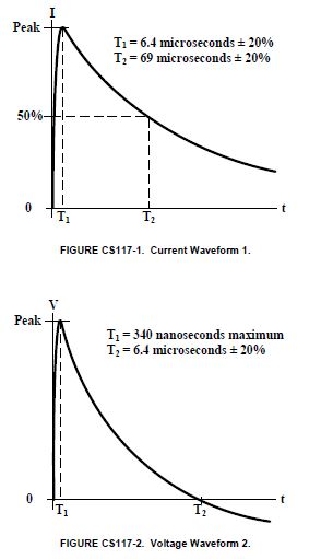
I have used AM26LV31E & AM26LV32E in my designs. I want to know whether these components are complied with either MIL-STD-461G or DO-160G standards? Especially Lightening tests, where Multiple stroke voltages & currents will be induced on the cable bundle of RS422. Please suggest. Our design is refers to the Internal Equipment Levels in the table below.
Thanks & Regards,
Raghavendra
Hi Ravi,
Please find below.
Multiple Stroke |
|||
Applicability |
Test Description |
Internal Equipment Levels** |
External Equipment Levels** |
All equipment installations |
Waveform 2 (WF2)/ Waveform 1 (WF1) |
First Stroke VL = 300 V (WF2) IT = 600 A (WF1) IT = 60 A* Subsequent Strokes VL = 150 V (WF2) IT = 150 A (WF1) IT = 30 A* |
First Stroke VL = 750 V (WF2) IT = 1500 A (WF1) IT = 150 A* Subsequent Strokes VL = 375 V (WF2) IT = 375 A (WF1) IT = 75 A* |
All equipment installations |
Waveform 3 (WF3) – 1 MHz and 10 MHz |
First Stroke VT = 600 V (WF3) IL = 120 A (WF3) IL = 24 A* Subsequent Strokes VT = 300 V (WF3) IL = 60 A (WF3) IL = 12 A* |
First Stroke VT = 1500 V (WF3) IL = 300 A (WF3) IL = 60 A* Subsequent Strokes VT = 750 V (WF3) IL = 150 A (WF3) IL = 30 A* |
Equipment installations routed in areas with composite skin/structure. |
Waveform 4 (WF4)/ Waveform 5A (WF5A) |
First Stroke VL = 300 V (WF4) IT = 1000 A (WF5A) IT = 300 A* Subsequent Strokes VL = 75 V (WF4) IT = 200 A (WF5A) IT = 150 A* |
First Stroke VL = 750 V (WF4) IT = 2000 A (WF5A) IT = 750 A* Subsequent Strokes VL = 187.5 V (WF4) IT = 400 A (WF5A) IT = 375 A* |
Multiple Burst |
|||
Applicability |
Test Description |
Internal Equipment Levels** |
External Equipment Levels** |
All equipment installations |
Waveform 3 (WF3) – 1 MHz and 10 MHz |
VT = 360 V (WF3) IL = 6 A (WF3) |
VT = 900 V (WF3) IL = 15 A (WF3) |
Equipment installations that utilize short, low impedance cable bundle installations. |
Waveform 6 (WF6) |
VL = 600 V (WF6) IT = 30 A (WF6) |
VL = 1500 V (WF6) IT = 75 A (WF6) |
Notes: *These current levels are intended for individual power leads or low count wire bundles. When multiple leads are tested together, this current shall be increased to the full bundle level or to the number of leads multiplied by the appropriate individual current test or limit level, whichever is less. **Amplitude Tolerance is +20%,-0% for all waveforms, except the tolerance is relaxed to +50%,-0% for the Subsequent Strokes. VT represents the test voltage level in volts and IT represents the test current level in amperes. VL (volts) and IL (amperes) represent limits intended to prevent over-stressing the EUT beyond the requirements. |
Regards,
Raghavendra
Raghavendra,
Are these stroke equipment level? Do you know what the stroke looks at the IC pins? These two devices are rated for IEC61000-4-2 standard, which stroke duration is in 100ns.
Regards,
Hao
Hao,
We would be injecting transients on shielded cable. But, I'm not sure about the transient levels reaching the device Pin. We are using TVS to protect the interface/device in our design. But, not sure whether TVS can save the device or not.
We have to impose cable injection lightning requirements of MIL-STD-461G CS117. The severity of the strokes are given below.
-Raghavendra
Raghavendra,
Thanks for your information. I understand the severity of the strikes, however how much energy reaches the IC pins depending on several factors like the cable impedance, device input impedance, capacitor between the shield and the wire, capacitor of the wire. Maybe you can do some rough estimate based on a simplified schematic. After that, you might be able to choose the proper TVS diode. Here are some reference about diode selection.
e2e.ti.com/.../how-to-choose-a-tvs-diode-for-rs-232-rs-485-and-can-based-on-voltage-ratings
Regards,
Hao