We are using the DS90UB949-Q1 and DS90UB948-Q1 ser/des pair to drive some displays in our IVI device. We are using BIST function on the DS90UB948-Q1 deserializer to check the FPD-Link quality and status during the device operation.
Result of BIST is on PASS pin so I want to read BIST PASS signal on deserializer pin 7 with oscilloscope.
PASS pin is shared with GPIO0 and SDOUT so I'm not completely sure that I read exactly PASS signal, and not GPIO0 value or SDOUT value.
What I did?
- First I set BIST_CONTROL(0x24) register on deserializer with value :
BIST_EN : 0
BIST_CLOCK_SOURCE : 01
BIST_PIN_CONFIG : 1 (I want to start BIST with BISTEN pin )
AUTO_OSC_FREQ : 1
BIST_OUT_MODE : 01
2. Then switch to port 0 and set GPIO0_CONFIG register to value:
GPIO0_DIR _D_GPIO0_DIR : 00 (Functional mode) - I expect to get PASS signal on pin 7
Rest of values in register are 0.
3. Then set D_GPIO0 (pin 19) to HIGH and D_GPIO[3:1] (pins 16, 17,
and 18) to LOW.
4. Set BISTEN pin to HIGH
5. Toggle 0x04[5] on the serializer. (MCU is on serializer side)
6. After 1 sec BISTEN pin is set to LOW
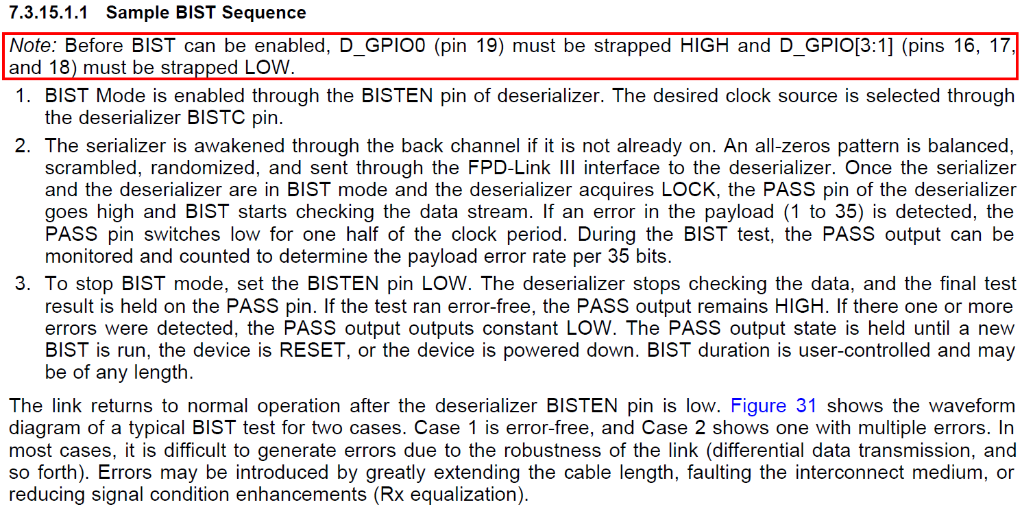
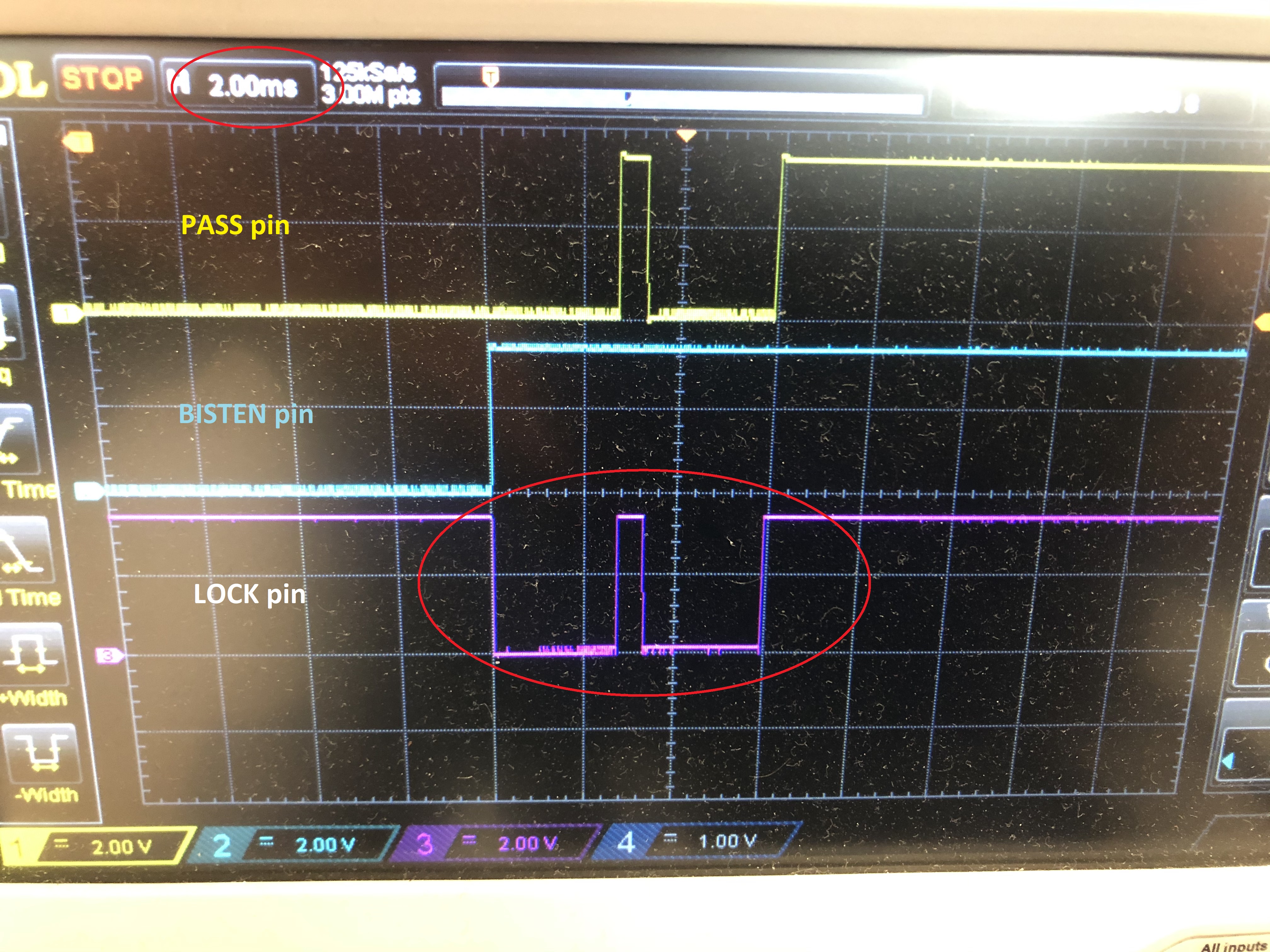
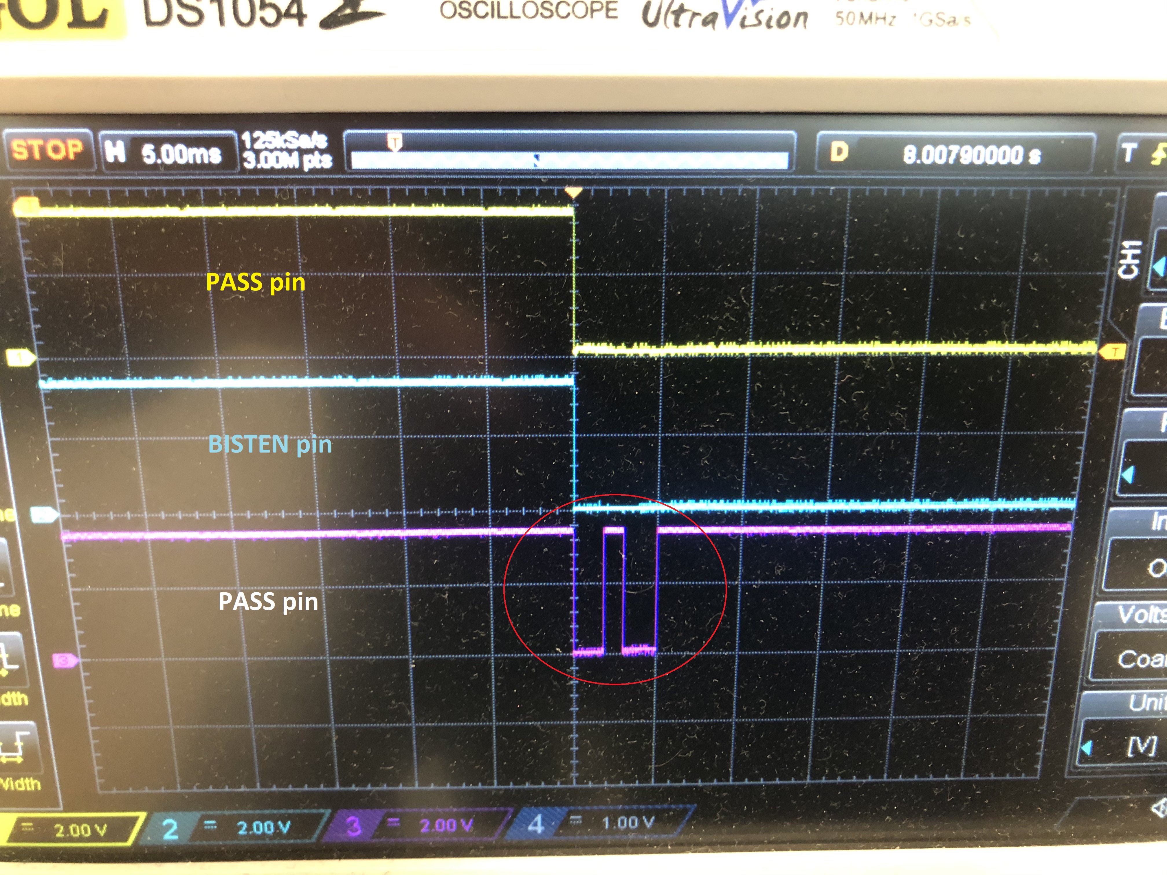
On the image below is what I captured.

Yellow signal is BISTEN pin and the purple one is signal on pin 7 on Deserializer.
I expect PASS signal on purple signal, but it's going LOW right after BISTEN is set to LOW and that is not what I expected.
Questions: Is the whole procedure right and how can I be sure that I read PASS signal?
If purple signal is PASS signal, why it's going LOW although there is no any LOW level in half-pixel clock period that means there is no error in BIST?
Also, after BISTEN is set to low, I’m trying to read some registers on Serializer and Deserializer via I2C. I managed to read serializer registers after that, but Deserializer and everything on I2C bus on DESER side Is not available. I don’t get ACK on I2C communication.
Thank you!
Best regards,
Tomislav