This thread has been locked.

If you have a related question, please click the "Ask a related question" button in the top right corner. The newly created question will be automatically linked to this question.

DP83867E: XI input parameters (thread continuation)

Expert 6500 points

Part Number: DP83867E

This links back to the following thread https://e2e.ti.com/support/interface/f/138/t/911513 

Hi Aniruddha,

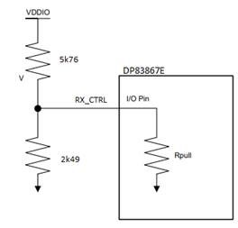
shared with you the schematic and below measurement results offline, per your request from the above thread. 

  1. DC biasing on XI pin without oscillator is 1.032V (CD1=CD2=27pF)
  2. Test with 2.5V clock from signal generator (CD1=27pF, CD2=16pF) – shared a scopeshot offline - CH1(yellow) is signal from generator, CH2 is XI input.
  • Datasheet requirement for XI input voltage above -0,3V is fulfilled (Meas. 7 (Base) = -271,5 mV)
  • Datasheet requirement for XI input voltage 1.5 - 1.9 Vpp is not met (Meas. 5 (Peak-to-Peak) = 1.394 Vpp)
  • Datasheet requirement for XI input high level >1.4 V is not met (Meas. 6 (Top) = 1.060 V)
  • Datasheet requirement for XI input low level <0.45 V is fulfilled (Meas. 7 (Base) = -271,5 mV)

Could you share your feedback what needs to be corrected?

Thank you.

  • Hi Bart,

    Thank you for sharing the schematics, I had some questions about few of the components used.

    We have not tested with a 50ohm resistor connected on CLKOUT pin of the PHY, it would be very strong pull down. I am evaluating the effect of the pull down resistor on the CLKOUT pin but can we check why it was added?

    MDC seems to have 100ohm pull up and 100ohm pull down resistors, are they both populated?

    For three supply configuration, is supply sequencing followed as per the datasheet?

    -Regards

    Aniruddha

  • Hi Aniruddha,

    thanks for your feedback / questions. 

    1. 50ohm resistor connected on CLKOUT: It was probably meant as 50R termination on CLK line. Agreed that it makes no sense here. We can remove this resistor for further tests, or turn off the CLK_OUT output in the registers.

    2. MDC pull-up/pull-down: Yes, both resistors are populated. It is Thevenin termination according to the recommendations for SMI bus routing, when more than one PHY is connected.

    3. Supply sequencing: The 1V8 voltage is directly derived from the 2V5 voltage line, so it tracking it with a minimal delay.

    Outside the discussion about XI - after the power-up, the test mode is active on PHY in conflict with the strapping pins setting.

    For example, on PHY described as Port 10 in schematic is following content in registers after power-up:

    Reg. CFG4 (addr. 0x0031): 0x10b0

    Reg. STRAP_STS1 (addr. 0x006e): 0x082a

    Reg. STRAP_STS2 (addr. 0x006f): 0x0100

    this corresponds to the strapping setting with the exception of bit[7] in CFG4.

    Although RX_CTRL is set to mode 3, the “Internal Test Mode 1” is active after power-up or reset.

    Looking forward for your feedback.

    Thanks & regards

  • Hi Aniruddha,

    could you share your feedback?

    Thank you.

  • Hi Bart,

    By removing the strong pull up on the clock output pin, do you see any improvement in the performance?

    MDC pull up and pull downs are not something that we have tested the device with, is this coming from the MAC side recommendation? This would need to be verified on the application.

    The most common reason for strap status not matching the desired strap values are some internal pull resistors on the MAC side. Can you check if any such pull resistors are present on the MAC side that can interfere with the strap resistors on the RX pins of the PHY? If there are then the external pull resistor values would need to be changed to bring the strap voltage within the acceptable region.

    -Regards

    Aniruddha

  • Hi Aniruddha,

    thanks for your feedback. 

    About MDC pull-up/downs – Yes, it is a recommendation from MAC manufacturer. We consider it to be a proven solution, because during the measurement we checked MDC and MDIO signals and we saw no problems. 

    About strap values – pin for this strapping option is “RX_DV_RX_CTRL” which is connected only to strapping divider, not to MAC.

    We will do the measurements (including strap votage) and let you know the results.

    Regards

  • Hi Aniruddha,

    we made the measurements:

    About strap values – Voltage on RX_CTRL pin is 453mV. Datasheet target voltage for mode 3 is (min./typ./max.) 405mV/459mV/511mV.

    In other words – required target voltage is 459mV±52mV. Measured voltage diverges from ideal value -11,5% of allowed tolerance.

    The rising edge on the reset pin comes much later (few seconds), because PHY reset is controlled by system software.

    Therefore, we believe that the incorrect reading of the configuration bit from strapping remains unexplained.


    About power sequence – Voltage rails ramp up with these delays: 2V5 <=1ms=> 1V8 <=5ms=> 1V1.

    It meets the requirements from the datasheet.


    About strong pull down on CLKOUT pin -  we made two screenshots of clock with and without 50R resistor.

    They are completely identical as you can see below:

    Before R1 removal: 


    After R1 removal:

    We have discovered one potential difference between our and your measurement.

    During our measurements, the PHY is in a reset state (because the measurement is done on a separate card removed from system).

    But when we released the RESET by changing the circuit, there was no observable change in clock signal behavior.

    Please advise, thank you for your support.

  • Hi Bart,

    Thanks for the additional information. When you release the reset from the device, the original voltage violation on the XI pin goes away. Is my understanding correct?

    Regarding PHY strap value, your calculation is correct. For 1.8V IO operation, 453mV operation should strap the device in mode 3. Can you monitor the RX_CTRL pin on a scope while you are apply reset to check if the voltage doesn't exceed 511mV as the reset pin is going high? Please continue to monitor at least 1-2 ms after the reset is released. 

    -Regards

    Aniruddha

  • Hi Aniruddha,

    unfortunately not, there is no change on XI pin based on state of RESET pin.

    We will make the measurements on RX_CTRL as you advised.

    Kind regards

  • Thanks Bart, understood. I will wait for your measurements.

    -Regards

    Aniruddha

  • Hi Aniruddha,

    here is the screenshot from oscilloscope with notes attached.As You can see, voltage on RX_CTRL grows slightly after RESET_N deassertion.

    We suspect this must be caused by the DP83867E, because nothing else is connected to the RX_CTRL signal. Only PHY and divider.

    The schematic looks like this:


    What we know (based on many measurements partially re-checked by a differential probe):

    • VDDIO 1V8 is clear and stable during startup
    • Voltage on RX_CTRL unexpectedly starts to rise 40ns after reset
    • All bits in registers based on strapping configuration are in expected state, except bit[7] of Configuration Register 4

    These facts make an impression that in RESET_N state the connection corresponds to the picture above with Rpull=9k8 (based on known values of external divider, VDDIO voltage and RX_CTRL voltage ). This corresponds to the information from the datasheet.

    But around 40 ns after RESET_N deassertion, the Rpull changes value to aprox. 80k which causes rise of RX_CTRL voltage to 530mV. This unexpected behavior is not mentioned in the datasheet.

    Then around 120ns after RESET_N deassertion, the RX_CTRL is internally switched to output. This unexpected behavior is not mentioned in the datasheet.

    Based on the information from the datasheet, and the timings:


    - the requirement for T4 is fulfilled because RESET_N is controlled from main CPU and deasserted a few seconds after system power up.

    But PHY behavior after RESET_N deassertion is totally different. At 120ns (where internal latch-in is expected) RX_CTRL pin is actively pulled low.

    So the problem remains unexplained and there are even more questions appearing.

    Looking forward for your feedback and support.

    Do you also have any further feedback about XI input problem? (this is also something we could not address yet).

    Thank you, kind regards

  • Hi Bart,

    I am looking into both the issues and will get back to you by Tuesday next week.

    -Regards

    Aniruddha

  • Hi Aniruddha,

    would you happen to have some feedback for us?

    Thank you.

  • Hi Aniruddha,

    is there any update from your side on that?

    Regards.

  • Hi Bart,

    We reviewed the validation data for the bootstrap modes and did not see any case in which the voltage on RX_CTRL jumps to 530mV in mode 3. By adding external resistors as explained in the datasheet the PHY was strapping correctly to mode 3. Are they 5.76kohm and 2.49kohm strap resistors 1% tolerance?

    For the behavior of the XI pin, again I did not find any instances where the PHY voltage was dropping to -0.38V. We are checking in design if this is acceptable. Have you performed any Packet Error test to check the Ethernet link performance? Do you observe data communication problems when the clock voltage drops below -0.38V?

    -Regards

    Aniruddha

  • Hi Aniruddha,

    Yes of course, 5.76kohm and 2.49kohm strap resistors are 1% tolerance.

    We have replicated the measurements of RX_CTRL voltage during de-reset on TI EVM. We found same voltage increase on RX_CTRL.

    Details about the measurement:

    • DP83867ERGZ-S-EVM without any modification is used.
    • Oscilloscope is triggered on RESET signal rising edge
    • Second channel is connected to RX_CTRL pin.
    • RESET is generated by button S1 on EVM

    As You can see on pictures attached below, there is a similar voltage increase on RX_CTRL when reset is deasserted (visible on zoomed waveform). Different voltage levels opposite to measurement on our card are caused by higher VDDIO used on EVM (2V5 vs. 1V8 on our card).

    But when we compare both voltage increases, they are definitely same – increase is 15% of voltage before reset deassertion, and length is 65ns before signal goes to logic low state. As we say earlier – reason can be only inside the chip, because there is only R7/R9 divider on pin.

    In this context – can You explain why divider use different R7 value then recommended in datasheet? (6.04k used vs. 5.76k recommended, which mean near to 5% difference).

    About Ethernet link performance: Yes, we observe some data communication problems, but the problems are rare.

    They manifest as SGMII link loss on peer (Ethernet switch fabric) few minutes after power-up.

    This problem can be mitigated by disabling SGMII auto-negotiation, but we still have not identified a root cause.

    We have tried:

    • Various clock levels by changing values of capacitive divider – with no effect
    • Disabling unexplainably activated internal test mode (related with RX_CTRL strap problem) – with no effect

    To avoid speculation about quality of our PCB design we would like to say that we use 5Gbit/s (5G-BASE-R) long links in our system without any problems.

    So we believe that short SGMII links between Ethernet switch fabric and DP83867Es are routed appropriately.

    We look forward to your feedback.

    Thank you.

  • Hi Aniruddha,

    our customer did a test with our EVM, below are the notes. Can you please help?

    I made next test related to RX_CTRL strapping. During the test, the TI EVM was connected by SMI to our system SMI bus.

    After turning on EVM, the DP83867E CFG4 register was read. Read value is 0x10B1 which means that INT_TST_MODE_1 bit is set.

    To remind you - the EVM setting of RX_CTRL strap is Mode 3.

    According to the datasheet, INT_TST_MODE_1 bit has to be reset, when Mode 1 or 2 is strapped (information based on datasheet page 38, note 1 under Table 6 ).

    It also implies that a bit is reset, when Mode 2 or 3 is selected. But in reality, the bit is after power-up always set until the CPU turns it off.

    The behavior is the same on our board and on your EVM.

    So there is a question if anyone is really trying to solve problems which we have described..?

    Let’s recapitulate it:


    We described voltage jump on RX_CTRL

    – You wrote that voltage jump has never been observed by TI team

    – and later we demonstrated a voltage jump on the EVM.


    We described unexpectedly set bit in Mode 3

    – You wrote that during your test PHY was strapping correctly to mode 3.

    – and later we read unexpectedly set INT_TST_MODE_1 bit in Mode 3 on the EVM.


  • Hi Bart,

    Thanks for the additional feedback. I think there might be a documentation issue with the register 0x31 bit[7]. Based on the observation, this bit needs to be cleared only when mode 1 or 2 is used on RX_CTRL strap and for strap mode 3/4 it can be ignored. I will check back on this bit behavior to confirm this documentation issue.

    Regarding the voltage jump, I had tried to re-create the issue on the test bench but I was using a different test board. I will try to repeat this measurement using the same EVM that you have used above. I think I should have an update for you by end of the week.

    -Regards

    Aniruddha

  • Hi Bart,

    I was able to verify the operation of register 0x31[7] and I can confirm that there is a typo in the datasheet. This bit does not show the current strap value of the internal test mode. This bit is a masking bit for the internal test mode. If the test mode is activated using strap mode 1/2 of RX_CTRL then register 0x31[7] can be used to allow or block the mode. If it is 1, then test mode is allowed and if 0 then test mode is blocked. If RX_CTRL is strapped in mode 3/4, then the test mode is disabled completely and in such cases register 0x31[7] bit is ignored. So, even if you strap the PHY correctly, register 0x31[7] will continue to say '1' but the test mode will not be active.

    There is another register bit that can tell you if the internal test mode is strapped correctly or not. Register 0x6F[8] is the internal test mode strap status bit. If this bit is '1' then the test mode is disabled and if this bit is '0' then test mode is enable. If RX_CTRL is correctly strapped to mode 3 on your application then you should read this bit back as '1'.

    Regarding the voltage spike on RX_CTRL, I tried using a DP83867 SGMII EVM in our lab and repeated the test setup. I tried multiple resets, but I could not observe any voltage spikes. I tried around 30 manual resets while monitoring the RESET line and voltage at RX_CTRL pin via oscilloscope. Was this fairly repeatable on your setup?

    -Regards

    Aniruddha

  • Hi Aniruddha,

    yes, measurement is repeatable. Are You sure, that You have appropriate setting of oscilloscope? Questionable part of signal is only 65ns long.

    But I think the problem of the RX_CTRL strapping can be considered as solved. From my point of view it is misinterpretation based on errors in datasheet. Concretely, 0x31[7] bit value is not based on strapping, as datasheet says, because strap value is saved in 0x6F[8] bit, which is described as reserved. Now we are believe, that 0x6F[8] bit is strapped correctly although analog behavior of RX_CTRL pin after RESET does not match description in datasheet.

    Problems with XI clock input stays unsolved.