This thread has been locked.

If you have a related question, please click the "Ask a related question" button in the top right corner. The newly created question will be automatically linked to this question.

DP83822I: Interface forum

Part Number: DP83822I

Continual discuss for the topic: DP83822I eye test failure(Twisted Pair Active Output Interface template):  https://e2e.ti.com/support/interface/f/138/p/934624/3456264#3456264

We tried to short L800 but still failed;

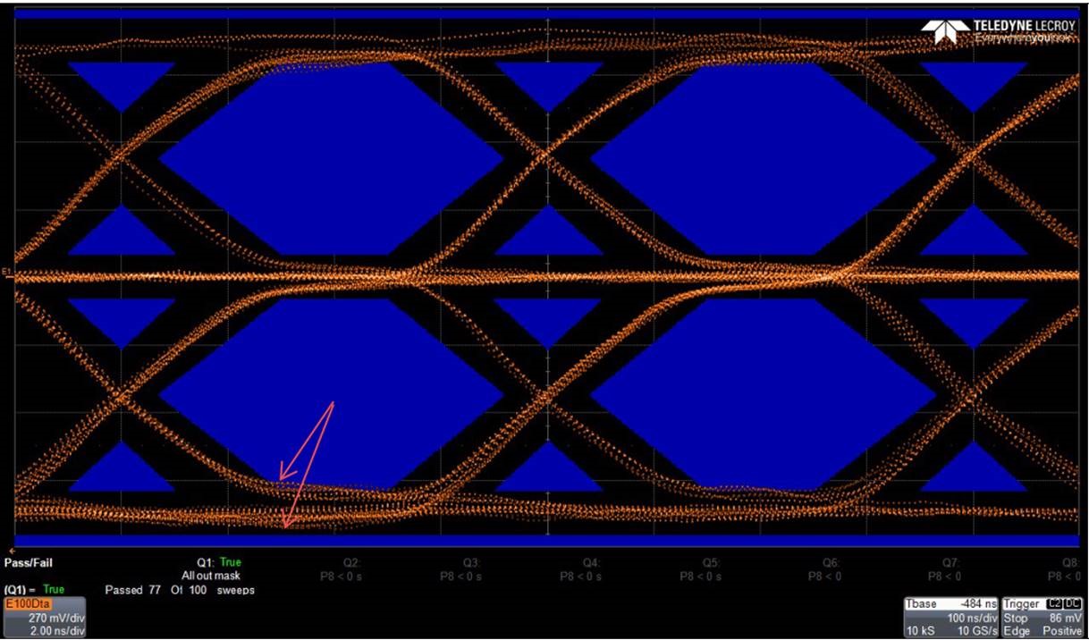
We also optimised the PCB and FPC layout but still failed, pls. ref. to attached test report.

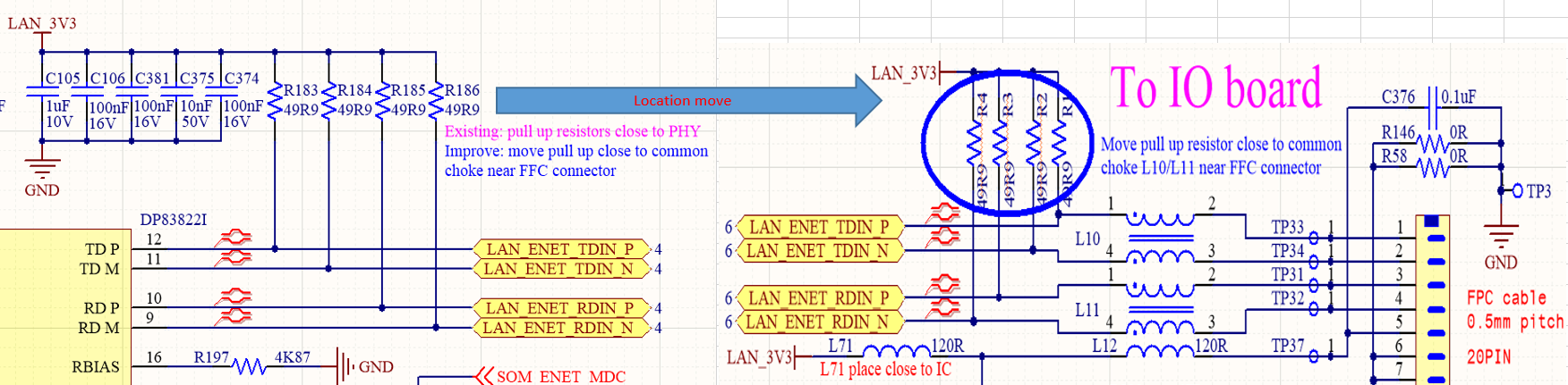
One question, what parameter causes this failure? noise on signal or rise/fall time or other parameter? can we modify 49.9ohm pull up to improve it?

BTW: we designed similar PHY circuit with another solution/IC, even using much longer FPC and PCB traces, but always get pass result;

  • Hello,

    I am looping in Justin who supported you previously on this debug.

    Justin- can you please take a look at this compliance testing result?

    Thanks,

    Cecilia

  • Hello,

    Can you please describe what was done to optimize the PCB and FPC layout? What is the length of connections between the PHY and the compliance test fixture? Impedance mismatches is a contributor to failures seen during this test, minimizing the impedance discontinuities can help improve the results. 

    Regards,
    Justin 

  • Hello Justin,

    The trace length between the DP83822 and Main PCB connector J4A is 151mm, the length of FPC cable is 150mm to IO PCB J4B, the trace length between J4B and RJ45 is 30mm.So the length between the DP83822 and RJ45 is about 331mm, then use a 180cm Ethernet cable connects to test board RJ45;

    We optimised the lenth matching for both PCB and FPC, and also well impedance control on fabrication, but seems no help.


  • Hello Justin,

    We tried to move 4pcs 49R9 pull up resistor close to common chock near to FPC connector, we found it can pass eye diagram testing mosttimes.

    But according datasheet we should place it clsoe to PHY, so pls. Justin help to check if any side effects for such modification?

    And why it better?

  • Hello,

    Moving the pull-up 49.9ohm resistors toward common mode choke is acceptable in this application. Do you have an transformer along the MDI path between the PHY and RJ45? Is the RJ45 integrated with a magnetic component?

    Regards,
    Justin 

  • Hello,

    Yes. the RJ45 jack integrats with a magnetic component.

    We had tried different RJ45 but same failure.

    Thanks!

    Harley

  • Hi Harley,

    As I discussed earlier, the Ethernet compliance tests are meant to test the PMA output performance of the PHY. To do this, the test setups are specified to minimize the impedance discontinuities and cable lengths to test the output of the PHY without introducing additional sources of noise and error. With this said, I would not consider the failures described above as compliance failures of the PHY given the multiple cable and connector points between the PHY and the test fixture. 

    We can continue to offer schematic and layout guidance to maximize the performance of the application.

    Regards,
    Justin