Hi TI Expert,
1.During the debugging of our product, it was found that when the device was just electrified and configured DS90UB953 by I2C, I2C would give a probablly wrong report. There was no problem with I2C accessing DS90UB954, but it was suspected that there was a problem with data transmission. We used the shielded twisted pair cable, but the board end was a common connector. Have you encountered any similar problems? below is the topo.
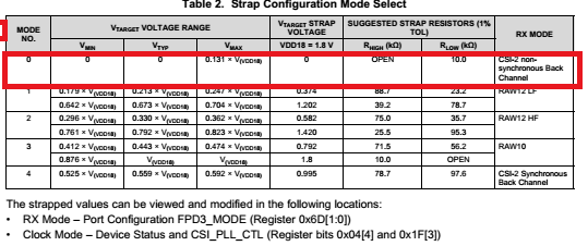
2. DS90UB953 is configured with Mode3, DS90UB954 is configured with mode 0, is there any problem with such configuration?
DS90UB953:
DS90UB954:
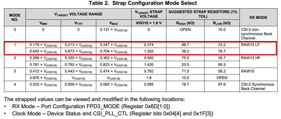
3. If single-ended coaxial cable is used, what should be the mode selection of DS90UB953 and DS90UB954? In the red box below, there are two configurations for each mode, what is the difference?
In addition, the software can modify registers to configure the mode, then which should we use to? software configuration or use hardware pull up and down?
Thanks & wait for you.


