This thread has been locked.

If you have a related question, please click the "Ask a related question" button in the top right corner. The newly created question will be automatically linked to this question.

DS90UB948-Q1: Clk and data jitter standard

Part Number: DS90UB948-Q1


Hi team,

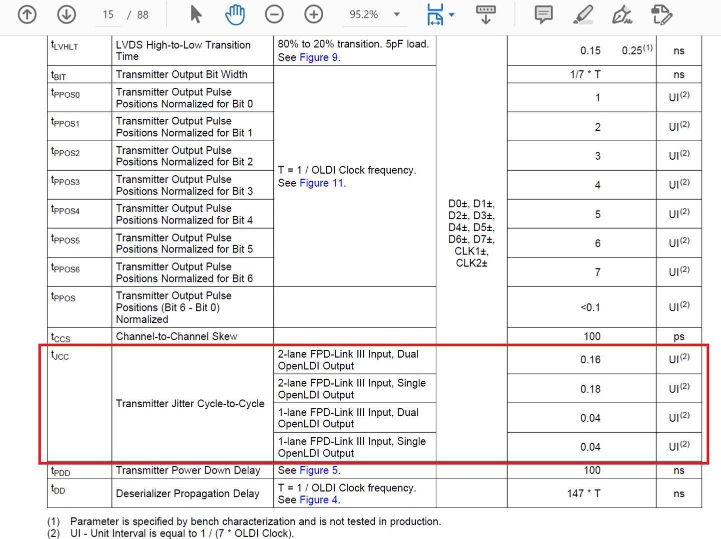
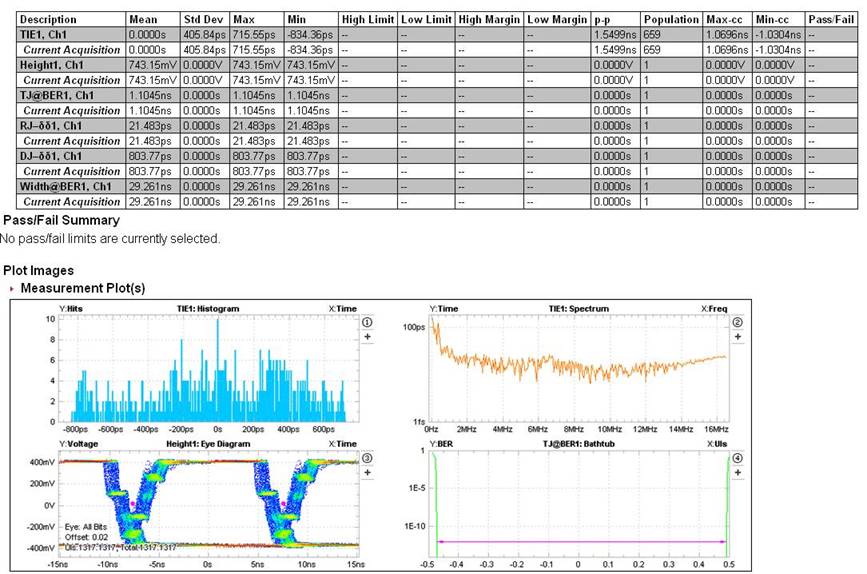
My customer has been testing UB948 output jitter as attachment.

Could you please help to check if the 0.16UI is for data for clk from datasheet?

Could you also help to check the jitter is okay for the test result? (Pclk=89MHz, 1920*1080*60)

Customer is testing with 2 lane FPDlink and Dual OLDI output.

Thanks.

  • Hello James,

    For measuring the OLDI jitter, please make sure to use the following scope settings for the clock recovery:

    Signal Type: Clock 

    Clock Edge: Rise

    Method: PLL - Custom BW

    PLL Model: Type II

    Damping: 700m

    Loop BW: 1MHz 

    Target BER = 1e-10

    Can you verify the jitter using those settings and then we can review?

    Best Regards,
    Casey 

  • Hi Casey,

    I would double check the test condition and get back to you later.(Where could I found these standard in datasheet?)

    But I want to understand that 0.16UI in red circle, is it for clk jitter or for data jitter?

    Thanks.

  • Hello James,

    The jitter spec is measured on the OLDI clock. To get the clock to data relationship you would measure the skew if needed between CLK and each of the data lines. 

    We are planning to generate an app note regarding the scope settings for measurement of OLDI interfaces which will include the information above. 

    Best Regards,

    Casey 

  • Hi Casey,

    Thanks for the prompt rely.

    So this is for the clk jitter, is that correct?

    In this case, they have dual OLDI ouput with PCK=45MHz(each clk), and 1 UI= 1/(45MHz*7)=3.175ns;   0.16UI= 0.5ns.

    But from the test result, the total jitter is 1.1ns, so in this case, they couldn't meet the requirement, is this correct?

  • Hey James,

    You need to apply the clock recovery settings first to make sure the measurement is using the same type of jitter metrics that the datasheet has. 

    Also, typically the jitter requirement for 948 output is based on the OLDI sink side (what is attached to the 948 output). What is the jitter spec for the sink device here?

    Best Regards,

    Casey 

  • Hi Casey,

    I have two question as below:

    1. What do you mean by clock recovery setting?

    2. I agree with you that the display side should have some requirement for this jitter. But my questions is that on our datasheet, we have this 0.16UI in our spec, what's the meaning of it?

    Thanks.

  • Hello James,

    Clock recovery settings are the settings I provided to you for the scope in my previous message. 

    The jitter spec is a typical spec as you can see from the datasheet. When you are doing system qualification, your jitter requirement should be based on the sink device you are driving. Typically the scope clock recovery settings which you use to measure jitter are based on the PLL characteristics of the device which you are driving into. That way you can get an accurate representation of what the sink side device will see based on the type of PLL which is used. 

    Best Regards,

    Casey 

  • Hi Casey,

    With the scope setting as you mentioned, should I keep the display screen connected, or disconnected?

    Do you have a typical standard from the sink device that would require for the jitter?

    Thanks.

  • Hello James,

    yes you need to have the sink device connected, including the 100 ohm terminations, as per the datasheet.

    unfortunatelly, we do not have any typical standard for a sink device. you should be able to get these from the datasheet of your sink device.