This thread has been locked.

If you have a related question, please click the "Ask a related question" button in the top right corner. The newly created question will be automatically linked to this question.

TPS65987D: USB Accessory Power role reversal with in data UFP mode

Part Number: TPS65987D
Other Parts Discussed in Thread: TPS65987,

Hi,

We are using TPS65987 in our android accessory design.

Following is the top level block diagram using TPS65987D.

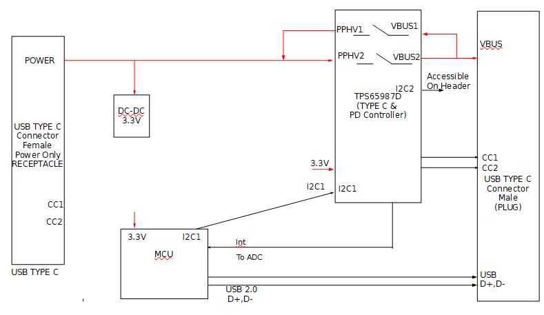
1. We are drawing the power from type c Receptacle connector and passing power through the android smartphone/Tablet using type c plug connector.

2. We have to keep our accessory in device mode (UFP) as smartphone/Tablet will be Host for data transfer. Power role should be dual role for sink and source.

If power adapter is there on receptacle connector than we required to charge the smartphone and if adapter is not there we need to sink the power from the 

smartphone.

3. So we would like to know in which configuration we can achieve this. Fast role swap is required to support this?

if yes than how can we achieve ?

  • Hi Paresh,

    What will you be attaching for the power receptacle? The power and data configurations should not be an issue but I am not sure if this will be compliant to the USB-IF specification document and requirements. Will this be mainly used to charge the Android smartphone?

    This type of design may not be feasible, but I will discuss with my team and get back to you next week.

    Thank you,

    Hari

  • Hi Hari,

    We are connecting usb type c power adapter which is used to charge the android smartphone. 

    Waiting for your input.

  • Hi Paresh,

    I believe the power pass through may work but only for a limited case such as only 5V on PPHV by connecting an external Rd.

    Unfortunately, if you are having 2 USB Type-C ports on your system then you would need either 2 PD/Type-C controllers or a dual-port controller. I also don't think you could support FRS. For FRS, you would also need another independent power source to become the supply in the case when the other power would be removed.

    Thank you,

    Hari

  • Hi Hari,

    Input is 5V coming from the receptacle connector by connecting Rd on this.

    And if we remove power adapter than we are planning to sink the power from the android smartphone by using FRS or barrel jack event as evm has shown.

    In this case can we need second PD or other power source ?

    Also we would like to know the time duration for the barrel jack event to perform the operation  so we can add the capacitance as required .

  • Hi Paresh,

    If that is the case where you will receive just a constant 5V on PPHV, I think it could work. There may be some other factors to consider as well though such as the behavior of the Android smartphone and if it would source power. In this case, you may be fine without a second PD though but I would recommend testing this on an EVM first.

    For the FRS timing, I believe the signal will pull down on CC for about 60us to 120us. I would recommend reading the FRS Application Note and the FRS White Paper for more detailed information.

    Thank you,

    Hari

  • Hi Hari,

    Can you please share the  default project file of GUI to use  in our application by doing customization  ?

  • Hi Paresh,

    Yes I can provide you with a default configuration project tomorrow but if you have the latest GUI tool for the TPS65987D, you should be able to choose your device and a few questions and you will get the default values. You may only need to change a few registers for your application, such as Transmit Source/Sink Capabilities, Port Control and Port Configuration. 

    Thank you,

    Hari

  • Hi Paresh,

    Please see the attached project file for default configurations set up for source and UFP.

    8611.TPS65987D_UFP.pjt

    Thank you,

    Hari

  • Hello Hari ,

    Working with Paresh on same project . We have few queries as mentioned below . Currently we have purchased 2 EVM for testing the below requirement .

    Requirement : Power Role Swapping ( FRPS & PRS ) feature without change in data role as described by Paresh in few queries back . 

    EVM 1 : 

    1) Data Role - USB Host / DFP Mode ( Fixed , No Change Required for our scenario ) 

    2) Initial Power Role - Sink 

    EVM 2 :

    1) Data Role - USB Device / UFP Mode ( Fixed , No Change Required for our scenario ) 

    2) Initial Power Role - Source ( Shall be change / shall perform PWR Role Swap  based on Barrel Jack Event )

    In case of no Power at Barrel Jack - Shall act as Power Sink

    In case of Power at Barrel Jack - Shall act as Power Source

    Can you please provide default configuration files to accelerate our testing of the barrel JACK event feature on EVMs Setup . 

    Thanks in advance .

    Anil

  • Hi Anil,

    Yes I can create a sample configuration project or if the settings match to your application, provide the default project. I will update this thread with the project file tomorrow.

    Thank you,

    Hari

  • Hi Hari,

    Please find attached project file for your reference.

    Following is  the observation when we test the FRS on evm.

    We have seen FRS timing 100ms to swap the power from source to sink when we remove the barrel jack.

    In this test we have used two evm board with FRS Configuration.

    As per datasheet it should be in micro Second timing FRS will take place.

    Please let us know if any change is required in project file to reduce this timing.

    mobile_pre_sink_FRS_1TX_1RX_FSRsupported_andvance.pjtacc_prefer_src_FRS_1TX_1RX_adv.pjt

  • Hi Paresh,

    The project files look ok to me, I can try to double check but would you be able to send me the scope captures of the CC and VBUS pins?

    Also do you have any PD logs from your testing that I could look at?

    I saw that you had used GPIO21 for the Barrel Jack event, but what did you connect this GPIO signal to for the input on the external circuit?

    Thank you,

    Hari

  • Hi Hari,

    Please find attached USB PD Log for your reference.

    Yes in evm there is a comparator circuit to detect the barrel jack connect and disconnect on GPIO21 so we have used GPIO21.

    Following is the screenshot from the evm schematic of TPS65987D:

  • Barrel Jack event:

    PGOOD is connected to GPIO21.

  • Hi Paresh,

    Could you please try reuploading the images and the PD logs again? It doesn't seem like they are viewable from your previous reply.

    Thank you,

    Hari

  • Hi Hari ,

    Please find attached log and image of evm schematic for barrel jack event.

    PGOOD is connected with GPIO21 for detect barrel jack.

    6661.mobile_pre_sink_FRS_1TX_1RX_FSRsupported_andvance.pjt4274.acc_prefer_src_FRS_1TX_1RX_adv.pjt

  • Hi Hari,

    Attached is the USB PD log for your reference..

    Port 1	Module 31	0x1ff = UNKNOWN
    Port 0	Protocol	0xc8 = PRState_TXDONE
    Port 0	Protocol	0xc5 = PRState_RX_BUF_RDY
    Port 0	Protocol	0xcb = PRState_RECEIVED_GOODCRC
    Port 0	PD	0x1c = PEState_Source_TransitionSupply
    Port 0	PD	0x1e = PEState_Source_TransitionSupply_SetAlarmsNew
    Port 0	PD	0x1f = PEState_Source_TransitionSupply_PS_RDY
    Port 0	Protocol	0xc8 = PRState_TXDONE
    Port 0	Protocol	0xc5 = PRState_RX_BUF_RDY
    Port 0	Protocol	0xcb = PRState_RECEIVED_GOODCRC
    Port 0	PD	0x17 = PEState_Source_Ready
    Port 0	Protocol	0x30 = PRState_Source_SinkTxOk
    Port 0	PD	0x31 = PRState_Source_SinkTxNG
    Port 0	PD	0x36 = PEState_PRS_Send_PR_Swap
    Port 0	Protocol	0xc8 = PRState_TXDONE
    Port 0	Protocol	0xc5 = PRState_RX_BUF_RDY
    Port 0	Protocol	0xcb = PRState_RECEIVED_GOODCRC
    Port 0	Protocol	0xc5 = PRState_RX_BUF_RDY
    Port 0	PD	0x5 = PEState_SoftReset
    Port 0	Protocol	0xc8 = PRState_TXDONE
    Port 0	Protocol	0xc5 = PRState_RX_BUF_RDY
    Port 0	Protocol	0xcb = PRState_RECEIVED_GOODCRC
    Port 0	PD	0x9 = PEState_SoftReset_Exit
    Port 0	PD	0x16 = PEState_Source_SendCapabilities
    Port 0	Protocol	0xc8 = PRState_TXDONE
    Port 0	Protocol	0xc5 = PRState_RX_BUF_RDY
    Port 0	Protocol	0xcb = PRState_RECEIVED_GOODCRC
    Port 0	Protocol	0xc5 = PRState_RX_BUF_RDY
    Port 0	PD	0x19 = PEState_Source_NegotiateCapability
    Port 0	PD	0x1b = PEState_Source_TransitionSupply_Accept
    Port 0	Protocol	0xc8 = PRState_TXDONE
    Port 0	Protocol	0xc5 = PRState_RX_BUF_RDY
    Port 0	Protocol	0xcb = PRState_RECEIVED_GOODCRC
    Port 0	PD	0x1c = PEState_Source_TransitionSupply
    Port 0	PD	0x1e = PEState_Source_TransitionSupply_SetAlarmsNew
    Port 0	PD	0x1f = PEState_Source_TransitionSupply_PS_RDY
    Port 0	Protocol	0xc8 = PRState_TXDONE
    Port 0	Protocol	0xc5 = PRState_RX_BUF_RDY
    Port 0	Protocol	0xcb = PRState_RECEIVED_GOODCRC
    Port 0	PD	0x17 = PEState_Source_Ready
    Port 0	Protocol	0x30 = PRState_Source_SinkTxOk
    Port 0	PD	0x31 = PRState_Source_SinkTxNG
    Port 0	PD	0x36 = PEState_PRS_Send_PR_Swap
    Port 0	Protocol	0xc8 = PRState_TXDONE
    Port 0	Protocol	0xc5 = PRState_RX_BUF_RDY
    Port 0	Protocol	0xcb = PRState_RECEIVED_GOODCRC
    Port 0	Protocol	0xc5 = PRState_RX_BUF_RDY
    Port 0	PD	0x3a = PEState_PRS_TransitionToOff
    Port 0	PD	0x3c = PEState_PRS_TransitionToOff_Source
    Port 0	VBUS	0xcc = VBUSState_MON_HILO
    Port 0	VBUS	0x90 = VBUSState_MON_HI
    Port 0	VBUS	0xcc = VBUSState_MON_HILO
    Port 0	VBUS	0x91 = VBUSState_MON_LO
    Port 0	PD	0x39 = PEState_PRS_AssertRd
    Port 0	PD	0x3d = PEState_PRS_SourceOff
    Port 0	Protocol	0xc8 = PRState_TXDONE
    Port 0	Protocol	0xc5 = PRState_RX_BUF_RDY
    Port 0	Protocol	0xcb = PRState_RECEIVED_GOODCRC
    Port 0	VBUS	0xcd = VBUSState_OVP_UVP
    Port 0	VBUS	0xb7 = VBUSState_GOOD_FALLING
    Port 0	Protocol	0xc5 = PRState_RX_BUF_RDY
    Port 0	VBUS	0xcd = VBUSState_OVP_UVP
    Port 0	VBUS	0xb6 = VBUSState_GOOD_RISING
    Port 0	Type-C	0x61 = COMMON_STATE_ATTACHED_SNK
    Port 0	PD	0x21 = PEState_Sink_Startup
    Port 0	VBUS	0xcc = VBUSState_MON_HILO
    Port 0	VBUS	0x90 = VBUSState_MON_HI
    Port 0	PD	0x22 = PEState_Sink_Discovery
    Port 0	PD	0x24 = PEState_Sink_WaitForCapabilities
    Port 0	Protocol	0xc5 = PRState_RX_BUF_RDY
    Port 0	PD	0x26 = PEState_Sink_EvaluateCapability
    Port 0	PD	0x27 = PEState_Sink_SelectCapability
    Port 0	Protocol	0xc8 = PRState_TXDONE
    Port 0	Protocol	0xc5 = PRState_RX_BUF_RDY
    Port 0	Protocol	0xcb = PRState_RECEIVED_GOODCRC
    Port 0	Protocol	0xc5 = PRState_RX_BUF_RDY
    Port 0	PD	0x28 = PEState_Sink_TransitionSink
    Port 0	Protocol	0xc5 = PRState_RX_BUF_RDY
    Port 0	PD	0x29 = PEState_Sink_TransitionSink_PS_RDY
    Port 0	PD	0x2a = PEState_Sink_Ready
    Port 0	PD	0x34 = PEState_PD_Send_Custom_Message
    Port 0	PD	0x32 = PRState_Sink_SinkTxOk
    Port 0	PD	0xe = PEState_GetCap
    Port 0	Protocol	0xc8 = PRState_TXDONE
    Port 0	Protocol	0xc5 = PRState_RX_BUF_RDY
    Port 0	Protocol	0xcb = PRState_RECEIVED_GOODCRC
    Port 0	Protocol	0xc5 = PRState_RX_BUF_RDY
    Port 0	PD	0xf = PEState_GetCap_Rx
    Port 0	PD	0x2a = PEState_Sink_Ready
    Port 0	PD	0x72 = PEState_DFP_VDM_Identity_Request
    Port 0	Protocol	0xc8 = PRState_TXDONE
    Port 0	Protocol	0xc5 = PRState_RX_BUF_RDY
    Port 0	Protocol	0xcb = PRState_RECEIVED_GOODCRC
    Port 0	Protocol	0xc5 = PRState_RX_BUF_RDY
    Port 0	PD	0x73 = PEState_DFP_VDM_Identity_ACKed
    Port 0	PD	0x2a = PEState_Sink_Ready
    Port 0	PD	0x34 = PEState_PD_Send_Custom_Message
    Port 0	PD	0x32 = PRState_Sink_SinkTxOk
    Port 0	PD	0x75 = PEState_DFP_VDM_SVIDs_Request
    Port 0	Protocol	0xc8 = PRState_TXDONE
    Port 0	Protocol	0xc5 = PRState_RX_BUF_RDY
    Port 0	Protocol	0xcb = PRState_RECEIVED_GOODCRC
    Port 0	Protocol	0xc5 = PRState_RX_BUF_RDY
    Port 0	PD	0x77 = PEState_DFP_VDM_SVIDs_NAKed
    Port 0	PD	0x2a = PEState_Sink_Ready

    What is the expected time to to power role swap  using FRS ?

    As per datasheet it is in micro seconds but we are getting 100ms time to swap the power role.

  • Hi Paresh,

    I took a look at the PD state trace and it seems like it is only performing a PRS, which will take longer, not FRS. Could you explain the process and give steps of how you are testing this?

    I would also recommend for you to read the USB Type-C and PD specification document on the FRS process to make sure you are being compliant. If you are able to get a PD log showing the CC communication that would also help. You will need an analyzer such as the one from Total Phase.

    Thank you,

    Hari

  • Hi Hari,

    Following are the details for our setup to test with two evms:

    4010.acc_prefer_src_FRS_1TX_1RX_adv.pjt3034.mobile_pre_sink_FRS_1TX_1RX_FSRsupported_andvance.pjt

    Accessory Side: (Prefer as Source)
    ---------------------------------------
    1. Project File: acc_prefer_src_FRS_1TX_1RX_adv.pjt
    2. Port Configuration (0x28)
      - Port Configuration: DRP
      - Receptacle Type: Standard fully-featured USB-C receptacle
       
    3. Port Control (0x29)
      - PD mode: Normal PD Behavior
      - Process swap to Source
      - Initiate swap to Source
      - Process VCON swap
      - Initiate swap to UFP
    4. Transmit Source Capabilities (0x32)
      - Configured only 1 PDO with (5V and 3A)
    5. Transmit Sink Capabilities (0x33)
      - Configured only 1 PDO with (5V and 3A)
      - Fast Role Swap required USB Type-C Current: 5V, 3.0A
    6. PD3 Configuration Register (0x42)
      - Fast Role swap Supported
      - Fast Role swap init in mSec: 4 mS
    7. I/O Config (0x5C)
      - GPIO #21
        a. Mapped Event: Barrel Jack Detect Event
        b. GPIO Polarity: Direct-mapped Event
    Mobile Side: (Prefer as Sink)
    --------------------------------
    1. Project File: mobile_pre_sink_FRS_1TX_1RX_FSRsupported_andvance.pjt
    2. Port Configuration (0x28)
      - Port Configuration: DRP
      - Receptacle Type: Standard fully-featured USB-C receptacle
       
    3. Port Control (0x29)
      - PD mode: Normal PD Behavior
      - Process swap to Sink
      - Initiate swap to Sink
      - Process swap to Source
      - Process VCON swap
      - Initiate swap to UFP
    4. Transmit Source Capabilities (0x32)
      - Configured only 1 PDO with (5V and 3A)
    5. Transmit Sink Capabilities (0x33)
      - Configured only 1 PDO with (5V and 3A)
      - Fast Role Swap required USB Type-C Current: 5V, 3.0A
    6. PD3 Configuration Register (0x42)
      - Fast Role swap Supported
      - Fast Role swap init in mSec: 4 mS

    Please let us know if we have missed anything.

  • Hi Paresh,

    Thank you for the picture. I do not see a barrel jack on there, but it seems from the logs it is performing the PRS correctly.

    How do you test this setup? For example, are you powering the Mobile side and then you would like to plug in the Accessory side with the barrel jack and want to perform a PRS? This should be correct.

    Otherwise, this will not perform a FRS unless the barrel jack was already plugged in from the beginning, the mobile was the source and then suddenly it lost power in which case the FRS will be triggered. FRS only occurs when an external power source is removed, not necessarily provided.

    The USB PD Specification here will provide further details on the exact process: 

    Thank you,

    Hari

  • Hi Hari,

    We would like to perform the FRS when barrel jack removed from accessory side so mobile can start source instead of sink.

    So as per project file is there any any change required to perform FRS ?

    Or else can you please provide the project file to test FRS ?

  • Hi Paresh,

    I noticed one more setting that you had missing, in your Accessory project can you also check the Process Swap to Sink field in Port Control? 

    Other than that, your project file should work unless there is an error occurring. You should be able to see a similar behavior shown in Figure 4 and Figure 5 of the FRS Application Note

    Are you able to provide scope captures of VBUS and a PD capture using an analyzer such as the Total Phase PD Analyzer as it provides more info into what could be happening?

    Thank you,
    Hari