This thread has been locked.

If you have a related question, please click the "Ask a related question" button in the top right corner. The newly created question will be automatically linked to this question.

DS90UB954-Q1: DS90UB954-Q1 CML out pin eye diagram

Part Number: DS90UB954-Q1

Hello 

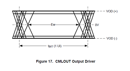
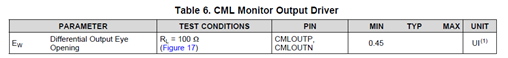
We tested the 90UB954 CMLOUT pin as attached. We only find one requirement in datasheet as below Ew < 0.45UI.

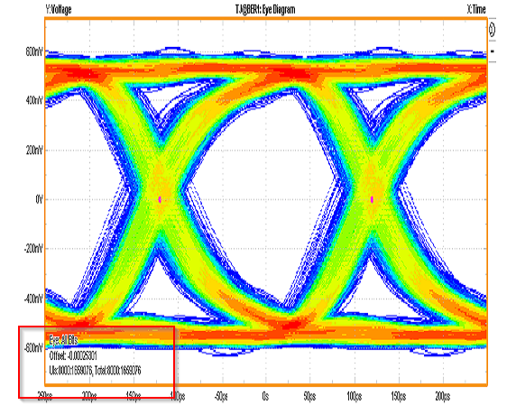
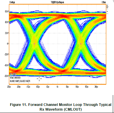
As calculated 0.45UI length 250ps * 0.45 = 112.5ps, we measured more than 150ps in eye diagram and believe it pass the spec. Does it accepted?

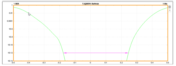
While some colleague suppose we need to use the value Width@BER1, Ch1 105.65ps to compare to 0.45UI( Ew in 954 spec)It is highly appreciated if it could be clarified. Thank you.

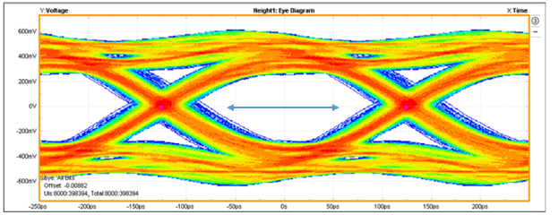
this is our test bathtub curve,   Width@BER1 is 105.65ps.
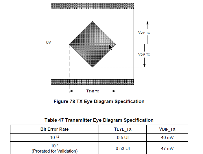
954 spec

Another thing is that in the 954 datasheet , there is a CMLout pin eye diagram, how can we get that eye-diagram? Does it use camera connect to the DUT via a coax cable , then open the equalizer in the 954 by setting resister., and set the loop BW as fpdlink_pclk /15 , then get the eye-diagram, right?

What is more , there is a input jitter requirement description in the 954  datasheet  for fpdlink signal, does it mean the requirement of RIN pin. What I know when the data signal from camera  to DUT  there is a long cable , the signal will be attenuated , then the eye diagram at the RIN is very bad , we can not make sure the jitter requirement on the RIN pin. Could you help explain?

Thanks,

Yumei

  • Hi Yumei,

    Please allow me some time to look into this. But judging from your measured eye, I believe you're meeting the spec.

    Instead of checking the CMLOUT eye, I would suggest running the margin analysis tool. It's a simpler and more accurate method  to check the health of the link. Please check the link below: 

    Best,

    Jiashow

  • Hello  Jiasow,

    I want to know if  the eye diagram Ew (0.45UI ) in the datasheet  is based on the specified BER(10^-12)?

    Because someone always think that the eye diagram in the datasheet is based on the specified BER.   I can not agree with that , so I need your help.

    My test step is using the jitter analyzer test template in the oscilloscope , then we can get the eye diagram->histogram->bathtub, so in the bathtub curve, we can get the width@ ber   value 105.65ps , this value is not the Ew in the spec ,right?


    Could you help answer these two color and bold words  question?


    Thanks,

    Yumei

  • Hi Yumei,

    Please allow me some time to take a look into this.

    Jiashow

  • Hi Yumei,

    Based on BER rate of 1e-12. Could you clarify your second question?

  • Hello Jiashow,

    what I mean is that different  Ber  has different Ew requirement like the MIPI eye template.

    if the ber is 1E-12,the Ew is 0.5UI,if the ber is 1E-6 ,then the Ew requirement is 0.53UI.

    As the showed picture in Ti datasheet , the left corner  of the eye diagram  Uis is 1689076, so what I mean the eye diagram is not based on 1E-12.

    Another thing is as the picture shows: if we want to get the 1E-9 ber eye diagram, and we want to to make sure the 95%  confidence , then the 3 times Uis  is enough.  3E9 bits.

  • Hello Yumei,

    Those specifications for BER vs UI are not related to FPD-Link. FPD-Link does not specify BER like this, so please do not use this kind of method for FPD-Link. This device targets a minimum BER of 1e-12 always based on its design and the eye opening on the TX side does not relate to BER like this. Based on the system design as long as it meets the high speed design requirements of the SER/DES, then most designs are able to achieve far better than BER 1e-12 as well.

    Best Regards,

    Casey