This thread has been locked.

If you have a related question, please click the "Ask a related question" button in the top right corner. The newly created question will be automatically linked to this question.

BOB SMITH TERMINATION

Need for Bob smith termination on both sides, especially in the LEFT SIDE  of the circuit, as there is dominantly DC voltage is appearing in the line (power line) which is centre tapped from the primary coils,inside the magnetics??? 
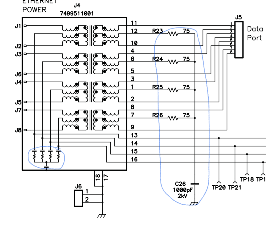
  • Hi User,

    The bob smith termination has multiple purposes. From a Power prospective, that is exactly correct, it blocks the DC so  that the resistors don't load each pair set.

    Thanks!

  • Hi Darwin,

    thanks for response..

    " it blocks the DC so  that the resistors don't load each pair set" which means that @left side, there is no need for a BOB SMITH termination.

    Since there will be no AC component is the line ( from primary coil center tap),  so BOB SMITH termination, which eliminate Common mode current RF emissions..etc, don't work with the DC line.

    Only DC component will be pulled out through the primary coil center tap, So that there is no need for BOB smith termination the left side (may be ESD capacitive termination is enough for the power line).

    Right????

  • Hi User,

    Just to be clear, bob smith termination is needed at the PoE front end (left side of your picture). It's mainly for the ethernet data to have matching impedances on both ends of the 100m ethernet cable. The caps help to block DC voltage on the ethernet cable from PoE from getting loaded and corrupting detection.

    You will see the bob smith termination on all PoE designs. Thanks! 

  • Hi Darwin,

    Thanks for response..

    1.To clarify the question part, in the front end, (left side part of magnetics), the primary part center tapped line, only DC part will be present (which is Power). Right??

    2. Also, data will be transferred to the right end, through magnetics, which is AC part (after coil induction through magnetics). Right??

    if both 1&2 are right, then Bob smith termination is only needed in the left part, Right part (front end) needs only ESD capacitors since its truly a DC power line.

    Thanks..

  • Hi User, I believe we are saying the same thing.

    The blue circle below is required while the red circle below is conditionally required. The red circle architecture will depend on the PHY that is chosen to process the ethernet data. Usually its data sheet will recommend the appropriate termination in the red circle.

  • Hi Darwin,

    Thanks for response..

    "The red circle architecture will depend on the PHY that is chosen to process the ethernet data. Usually its data sheet will recommend the appropriate termination in the red circle."

    Can you please tell me its dependencies? (I meant the PHY characteristics, .etc)

    Thanks..

  • HI User,

    Unfortunately my focus is mainly in power for PoE and not data so i'm not familiar with the data dependencies/PHY. You may want to check with the PHY forums. However, I will say when you open a datasheet for different PHYs, there is an application implementation for the ethernet data termination of the PHY side of the data transformer. Some datasheets use a cap/resistor combination while other datasheets have a direct voltage rail connection like to a 3.3V rail.

    Regards,

    Darwin