This thread has been locked.

If you have a related question, please click the "Ask a related question" button in the top right corner. The newly created question will be automatically linked to this question.

DP83869: AM335x to DP83869 interface

Part Number: DP83869
Other Parts Discussed in Thread: DP83640, ,

[Nick Saulnier]: Title & content edited Dec 15 2020 as per Anees's Dec 14 post

Hi All,

I am redesigning AM335x based OEM module to change the Brodcome PHY chip to a low-cost DP83640 DP83869 Phy chip.

Present  OEM module design,  We have used dual "BCM54616S" Broadcom 10/100/1000 Phy chip with the copper interface.  This Phy did not require dedicated  COL, RX_ER, and CRS. So we used the COL, RX_ER, and CRS dedicated pins of the AM335x controller for some other applications.

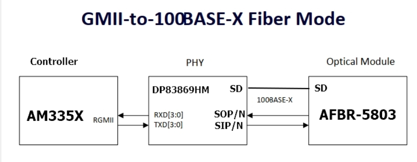
In the new design, We planning to use the DP83640 DP83869 Phy chip with a 100mbs fiber interface.

So please suggest a solution to interface the DP83640 DP83869 without COL, RX_ER, and CRS pin to the AM335X controller..

I have attached the schematic of DP83640 DP83869 with the fiber transceiver(AFBR-59E4APZ) interface.  

also please confirm, any option to use GPIOs or alternate pin for these functions (COL, RX_ER, and CRS)  in AM335x.

 SCHEMATIC1 _ AM335X_DP83640.pdf

SCHEMATIC1 _ AM335X_DP83640.pdf

  • Hi Anees,

    I would like to confirm the setup you are describing. The DP83460 CRS_DV, RX_ER, COL pins are available from the PHY perspective but these pins have been utilized in the AM335X's side? 

    The DP83460 can be configured for RMII mode where the COL and RX_ER are not required connections, but the CRS_DV pin will need to be connected to the MAC in this mode. 

    I am moving this thread to the processor team for their input in utilize other pins available in the processor for this use case. 

    Regards,
    Justin 

  • Hi Justin,

    Reply inline 

    I would like to confirm the setup you are describing. The DP83460 CRS_DV, RX_ER, COL pins are available from the PHY perspective but these pins have been utilized on the AM335X's side?

    Anees - Yes, these pins are used for SPI and UART interface from the controller side.  please refer to the below images. These pins are not required on the Broadcom side.


    The DP83460 can be configured for RMII mode where the COL and RX_ER are not required connections, but the CRS_DV pin will need to be connected to the MAC in this mode. 

    Anees - Processer side this pin also used. Any  option to in the Phy chip - DP83460, to configure this function though any other MII pins similar to Broadcom chip -AFBR-59E4APZ


    I am moving this thread to the processor team for their input in utilize other pins available in the processor for this use case. 

    Anees - OK, Please. 


    Thanks

    Anees PK

  • Hi Anees,

    As stated above, in RMII the CRS_DV pin is needed in the DP83640. I expect the BCM54616S device was connected in RGMII or SGMII where there is no CRS pin. 

    The DP83640 PHY cannot configure any other pin to carry the CRS signal, these pins and functions are defined by the RMII specification. 

    Regards,
    Justin 

  • Hi Justin,

    Yes, BCM54616S device was connected RGMII in the present design.

    Regards

    Anees PK

  • Hi Anees,

    Thank you for confirming, I am passing the thread to the processors team for their input on multiplexing a different pin to connect to the PHY CRS_DV pin.

    Regards,
    Justin 

  • Hello Anees,

    Are you using CPSW ports or PRU Ethernet ports?

    Regards,
    Nick

  • Hi Justin,

    Please check the  PHY chip-  DP83869HM part is suitable to interface AM335x with RGMII  and the PHY chip FIber Out /Input signal to the SC FO module ( AFBR-59E4APZ)   . Also, please refer to the below block diagram.


  • Hello Anees,

    Ok, so my understanding is that you want to move from RGMII with the broadcom PHY to RMII with the DP83640.

    Please reference the AM335x datasheet. It looks like the GEMAC_CPSW/RMII1 signals only have the crs_dv signal pinned out to one pin. However, GEMAC_CPSW/RMII2 can send the rmii2_crs_dv signal to two different pins. RMII is not supported on AM335x PRU Ethernet, only on CPSW Ethernet ports.

    Regards,

    Nick

  • Hi Nick,

    No sir, we want to move the RGMII with Broadcom PHY chip to RGMII with TI  DP83869HM PHY chip. And we need to connect the  DP83869HM  PHY chip to the Broadcom SC FO module ( AFBR-59E4APZ). Please conform to the same. 


    Regards

    Anees PK.

  • Hello Anees,

    Ok, got it. We were confused about the part number:  DP83640 in your original post supports RMII. RMII requires a crs_dv signal. DP83869HM supports RGMII. RGMII does not use CRS_DV, RX_ER, COL signals. I have updated your original post based on your Dec 14 post.

    I would expect that you could use the same AM335x signals for RGMII connections to BCM54616S and DP83869HM. I am going to reassign this thread back to the PHY team so they can comment if they have additional feedback.

    Regards,

    Nick

  • Hi All,

    I am awaiting your reply to the above clarification on the DP83869HM to SC-FO AFBR 5803 interface.

    Regards

    Anees PK.

  • Hi Anees,

    Yes, the AFBR-5803 is a suitable SFP for the DP83869HM device.

    Regards,
    Justin 

  • Hi Justin,

    OK, thanks,

    Also, please share the details of the Linux driver of DP83869 PHY to  AM335X  microprocessor.

    I will share the schematic for review.

    Regards

    Anees PK.

  • Hi Justin,

    I have attached the schematic of the schematic DP83869PHY chip and AFBR-5803 interface section with configuration also.

    Please find the below PHY configuration details and confirm the configuration is correct or not

    1.  Device PWR supply is 2 supply configuration but considered 1.8V section is  "No-load" in the design.
      Please confirm the 1.8VDC bus is required for the 100FX fiber interface. H
    2. Whether  AC coupling ca[acitir is required for FX OUTPUT signal to FIber transceiver module. Please check the 0.1uF added on the AFBR-5803 is OK or not. 
    3. PIN 24, JTAG_TDI pin configured as "Signal detect " of SC-FO transceiver Module by connecting the LED1(pin). Also please check the resistor value used for pull-up the pin is OK or not.
    4.  LED0 used for FO auto-negotiation. Please check the configuration also.
    5. Please confirm the RGMII to 100FX mode section resistor configuration 
    6. Please confirm the PHY address configuration "1010" using resistor strap values or ok. 
    7. Please confirm the unused JTAG pins need to pull-up or Pull Down
    8. How to set the LED one for FO to detect and the other for FO Activity module. It is set through software or the PIN strap method. Please confirm.
    9. How to disable the CLKOUTPlease find the attached schematic.

     SCHEMATIC1 _ 03 PHY_100FX SC_FO.pdf