This thread has been locked.
If you have a related question, please click the "Ask a related question" button in the top right corner. The newly created question will be automatically linked to this question.
TI_ETH_SCH.pdfHA-118BAGYZNL-GY(LAN_Connector).pdf
Dear TI,
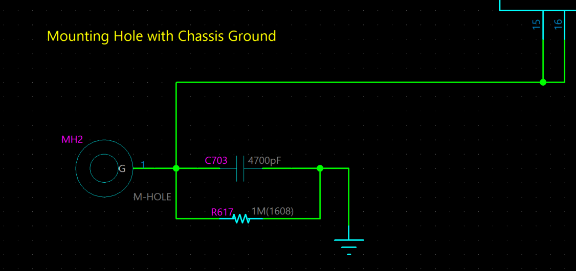
I atttach schematics Gigabit-Ethernet using DP83867IRRGZT.
(Net of 3V and 1_8V are connected another power circuits)
Please, Review & Comment.
Best Regards,
Inho Jeon
Hi Inho,
I am in the process of reviewing your schematic and will get back to you tomorrow with comments.
Regards,
Adrian Kam
Hi Inho,
Below are the comments/questions I have regarding your schematic:
Regards,
Adrian Kam
Dear Adrian,
Below this reply for your comment.
1. 3V is 3.296Vdc. Is that good?
2. I designed that circuits refer to ADI reference EV-KIT of schematics.(Below refer to linked website page 15 of 28). That EV-kit is working good.
www.analog.com/.../ADSP-SC589_EZ-Board_Schematic-Rel_2-0B.pdf
3. I attach "Add R.PNG". Is that right?
4. You mean not connect VCC of that RJ45. is that right?
And, I have additional question : Is that RJ45 connector need ESD
suppressor if not connected VCC of that part ?
5. Ok. I see.
Thank you.
Best Regards,
Inho Jeon
Dear Adrian,
In the DataSheet, the XI ranges from -0.3 to 2.1V.
If so, the OSC with 1.8V power supply can be directly connected to XI without Cap, isn't it?
And, the 33 ohm series resistance of XI is for damping purposes.
Thank you.
Best regards,
Inho Jeon
Hi there,
Adrian is currently out of the office. Please expect some delay in answers in the upcoming days during this holiday.
Thanks!
Hi Inho,
See below for my responses:
Regards,
Adrian Kam
Dear Adrian,
Thank you for reply.
I want to use 1.8V power for oscillator to save parts.
Is that designed circuits have working problems?
If it is, please inform me specifically.
And, I want to know why it could cause problems when connected to the VCC of RJ45 connector.(That part is I attached before)
Also,I want to know why not need to ESD suppressor for that RJ45 connector.
Thank you.
Best regards,
Inho Jeon
Hi Inho,
After discussing with my team more, allow me to correct some of my mistakes in my replies:
We have had issues in the past where not leaving the center tap floating causes some marginal IEEE compliance failures. As a result, we recommend leaving the VCC pin floating.
Regards,
Adrian Kam
Dear Adrian,
Thank you for your reply.
I don't understand your reply No. 2.
So, Reply for below my questions,please.
You mean that VCC port of RJ45 Jack is not need to connected "VDD_TI_ETH", Is it right?
And, You mean that VDD port of ESD suppressor(D35,D20: I attach that part datasheet) is need to connected "VDD_TI_ETH", Is it right?
Best Regars,
Inho Jeon
Hi Inho,
You are correct.
The VCC port of RJ45 should not be connected to "VDD_TI_ETH" or any other net. It should be left floating.
The VDD port of ESD suppressor should be connected to "VDD_TI_ETH".
Regards,
Adrian Kam
Dear Adrian,
Thank you for reply.
On datasheet, Supply Configuration is 2 ways.
But I don't understand about that.
So, please Inform me about "Two Supply Configuration" & "Three Supply Configuration specifically".
And, I want to know function of "VDDA1P8".
Thank you.
Best Regards,
Inho Jeon
Hi Inho,
For the DP83867, the "Two Supply Configuration" uses 1.1V and 2.5V supplies, while the "Three Supply Configuration" uses 1.1V, 1.8V, and 2.5V supplies.
The three supply configuration has an overall lower power consumption compared to the two supply configuration. Below is the link to an app note with power consumption data for the DP83867.
https://www.ti.com/lit/an/snla241/snla241.pdf?ts=1609955756478
For two supply, VDDA1P8 is left floating, but for three supply, an external 1.8V analog supply is connected to VDDA1P8.
If you have any other questions, please start another thread, as this thread has been resolved.
Regards,
Adrian Kam
Dear Adrian,
Thank you for reply.
I checked difference of current consumption for 2.5V on 2 supply ways.
And, Is it available comment & review for PCB artwork file?
Thank you.
Best Regards,
Inho Jeon
Hi Inho,
If you are referring to the PCB layout, then I can review that as well if you put the files in a reply.
Regards,
Adrian Kam
Dear Adrian,
I attach PCB & schematics files.(PCB file is designed with PADS LAYOUT)
Please, Review & Comment.
Thank you.
Best Regards,
Inho Jeon
Hi Inho,
I am in the process of reviewing the layout and will get back to you by EOD Friday at the latest.
Regards,
Adrian Kam
Hi Inho,
Below are my comments/recommendations on your layout:
It is possible that some of these recommendations may have already been done, but my layout editor did not properly import everything.
Regards,
Adrian Kam
Dear Adrian,
Thank you for reply.
Below this, I comments your answers for my PCB.
Please, reply for my comments.
And, on your comment, MII is RX_CTRL,RX_D3, RX_D2, RX_D1, RX_D0, RX_CLK / TX_CTRL, GTX_CLK, TX_D0, TX_D1, TX_D2, TX_D3, right ?
Thank you.
Best Regards,
Inho Jeon
Hi Inho,
Regarding number 5 on the list, it is more of a recommendation than a must. It is possible that this will not cause any issues, but if you do encounter issues with those signals, then the crosstalk could be a potential cause. Overall, I would recommend avoiding this situation if possible.
Yes, those are the MII signals.
Regards,
Adrian Kam
Dear Adrian,
Thank you for reply.
5-Layer of signals(that is acrossed MII traces of DP83867IRRGZT) is not high-speed signals. it is just logic signals for ON/OFF[3v/0v] conditions of peripheral devices.
So, I think it is not affect MII traces of DP83867IRRGZT.
How about your opinions?
Thank you.
Best Regards,
Inho Jeon
Hi Inho,
In that case, I agree with you in that it probably will not affect the MII traces. Also, looking closer, the traces seem to be mostly perpendicular to each other, which should reduce crosstalk further.
Regards,
Adrian Kam