Hi Sir,
may we learn and help from you, could help check this schematic and are there any suggestion or problem about this schematic?
This thread has been locked.
If you have a related question, please click the "Ask a related question" button in the top right corner. The newly created question will be automatically linked to this question.
Hi Sir,
may we learn and help from you, could help check this schematic and are there any suggestion or problem about this schematic?
Hello TI
Add the information...
The Host is from Intel Tiger lake UP3
and
the input is from SoC (TCP 1) that was programmed on GOP output format as Integrated HDMI/DVI.
Not "Integrated DP with HDMI/DVI Compatible" or "Integrated DP Only"
Hi,
1. There is no need to have an external pullup resistor on the OE pin, I would also change the pulldown capacitor from 0.1 to 0.22uF.
2. Please make sure the HDMI_RT_AUX_DP/DN are AC coupled
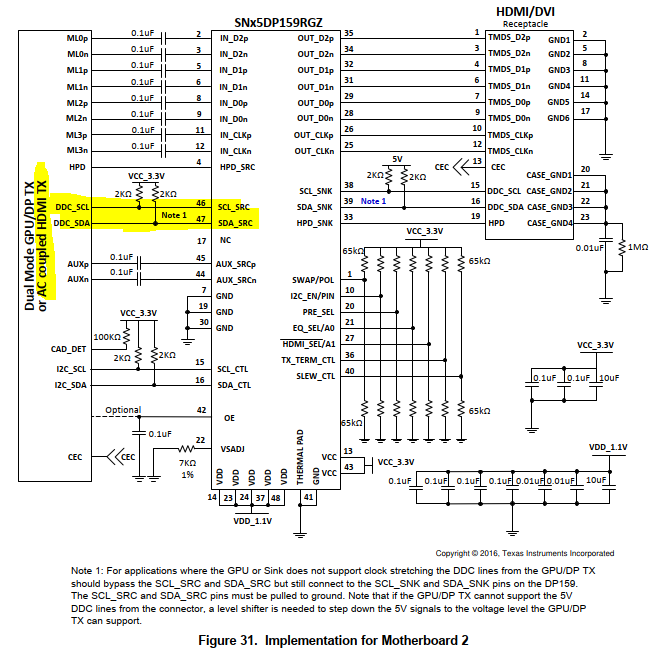
3. Does TGL support clock stretching on the DDC bus? If not, then you need to implement the DP159 DDC snoop mode. Please refer to section 9.4.4, particularly the note section for more detail.
Thanks
David
Hello David
1. There is no need to have an external pullup resistor on the OE pin, I would also change the pulldown capacitor from 0.1 to 0.22uF.
OK,I will remove R117 pull up resistor and modify the C70 0.1uF to 0.22uF.
2. Please make sure the HDMI_RT_AUX_DP/DN are AC coupled
Actually,
if the output from Intel set as HDMI, it only has DDC(CLK/DATA) to communicate to device(SN65DP159RGZ.).
There(GOP) is no AUX P/N interface option to communicate by using DP output.
The SN65DP159RGZ not only supports DP++ , but also AC HDMI couple intput.
So...why it(GPU) still need to link AUX P/N into SN65DP159RGZ ?
I upload the Intel TGL UP3 RVP circuit file to you as reference by using SN75DP159RGZT
and
I design the same circuit as my application.
Please kind help me checking, is it ok on my design ?
612304_TGL_UP3_LPDDR4x_RVP_SCH_Rev1p0_1.pdf
612304_TGL_UP3_LPDDR4x_RVP_SCH_Rev1p0_2.pdf612304_TGL_UP3_LPDDR4x_RVP_SCH_Rev1p0_3.pdf
Hi,
The implementation of DDC and I2C-over-AUX depends on the DP++ source. The DP159 is designed to support both implementations.
A dual-mode DisplayPort Source may implement I2C signaling only, allowing it to access Type 1 or Type 2 cable adaptor registers and the Sink-side DDC interface, and thus support both adaptor types.
Alternately, a dual-mode DisplayPort Source that support Type 2 cable adaptors only may implement AUX signaling only, and not I2C signaling. The type of cable adaptor(s) supported must be declared by the Source.
You can leave the DP159 AUX floating if not used.
Thanks
David
Hello David
All of you said were DP++ mode (type 1 & type2).
But I concern that ...
the INTEL output has been AC HDMI couple signals format which programmed by BIOS(GOP),
Should I just series connection 0.1uF on DATA pins and pull up 2k ohm to 3V3 on DDC pins to re-timer ?
And Keep AUX_P/N floating , then I will see the HDMI 2.0 4K/60hz on the monitor ?
Hi,
Using Fig 31 as a reference, you can see the source supports both DDC and AUX so both the DP159 DDC and AUX are connected to the source and the source can choose to communicate across either the DDC or the AUX.
If the source only supports DDC, then you can leave AUX open as shown in Fig 32 of the DP159 datasheet.
Thanks
David