This thread has been locked.

If you have a related question, please click the "Ask a related question" button in the top right corner. The newly created question will be automatically linked to this question.

TIOS1015: Detailled description of overcurrent limit / differentiate methode for NFAULT / hysteresis for thermal warning

Part Number: TIOS1015
Other Parts Discussed in Thread: TIOS101,

Hi,

in Thread "TIOS101: Over current failure" is mentioned, that with open Rset, fault reporting will be disabled.

Quote:

Also note that if the maximum current limit is configured via pulling RSET low, then you could use a switch (e.g., FET controlled by the MCU) to open RSET instead when a fault is detected.  Having RSET open sets the same current limit value but disables the fault reporting; so, if the fault did not repeat then you would know that it was an over-current fault.

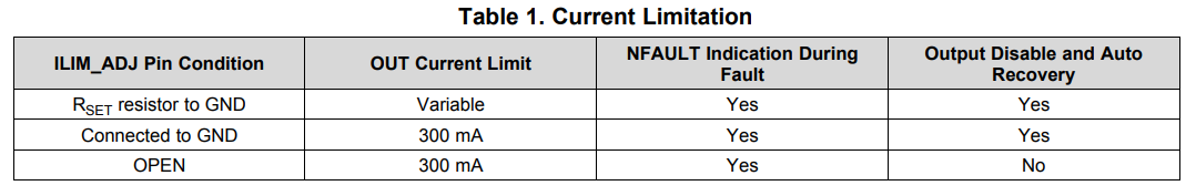
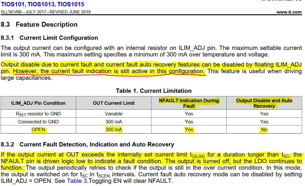
By switching a FET to float the Rset pin, you could differentiate between an overcurrent and overtemperature/undervoltage fault reporting. But in the datasheet, you can see, that with open Rset pin, only auto recovery mode will be disabled, but not the fault reporting. Fault reporting will always be active:

Is this a wrong description in the datasheet or wrong description in the mentioned thread?

Next question:

How does the Rlimit internally work? I assume that current is measured through a shunt and voltage will be compared with a feedback voltage, which is set by Rset. But, if current limitation works with settable voltage feedback through Rset, how does it work for Rset = GND ? Feedback voltage would be GND/zero in this case. Could you give me a detailled information about the internal structure of current measurement?

At the end of the day, I need an option to differentiate the overcurrent fault reporting from overtemperature and undervoltage. Undervoltage is not as important as overtemperature. We operate this devices at ambient temperatures about 120 degrees celsius, so with self-heating of the device, overtemperature fault could be active low in normal operating conditions. 

We have to prevent, that TIOS1015 will generate "false" signals to the OUT pin, which is the case in auto recovery mode. We could deactivate auto recovery mode, but then the TIOS1015 will heat itself up to the point where overtemperature shutdown will be active. Device will set the OUT pin to high impedance, but in this time, it cools down, and when reached the hysteresis (10 °C) it will turned on again, so you can see a temperature-specific frequency at the output. So this it not an option for us.

We would be quite happy, to detect an overcurrent condition which is not an overtemperature warning, and then shut down the device until it will be resettet. Microcontroller is available.

Last question:

What hysteresis does have NFAULT reporting for overtemperature warning? In datasheet, there is only described hysteresis for overtemperature shutdown, but not for overtemperature warning. If there is no hysteresis, will NFAULT oscillate at T(wrn) 125°C ?

Thanks and best regards,

Chris

  •  Sorry, picture upload didn't work properly at my first try.

  • Hi Chris,

    You are correct in your interpretation of the datasheet and leaving Rset open will turn off the Output Disable and Auto Recovery feature of the device, but the current limit is still set at the maximum value of 300mA.  Any current level that exceeds the set current limit will trigger the NFAULT.  In this case I would say that the other E2E thread you quoted is misleading.

    The Current Limit feature of this device can be easily misunderstood so I will try to clarify it for you.  The word "Limit" refers to a threshold and does not refer to a behavior. 

    First off, this device will not clamp or regulate current to any particular level.  It only compares the current and against the maximum allowed current threshold or "limit."  If the current exceeds this threshold for greater than Current Fault Blanking Time (Tsc = 200 uS typical), then the output driver will be disabled and a fault is reported.  Therefore the Rset resistor is used with an internal resistor to set a voltage threshold on the comparator which allows any current limit to be set up to 300mA.

    This particular device was not designed to clamp or restrict current flow in excess of a particular level.  This is also commonly referred to as a Current Limiter, and is a common feature of many devices.  In this architecture, a feedback loop is requires as you have described.  This can become problematic for complex inductive and capacitive loads that have a phase delay between the voltage and current which can lead to oscillations and stability issues where the output driver is repeatably turned on and off.

    The TIOS1015 will allow the higher inrush current before reporting a current fault after 200uS, but if this is not enough time, then the Output Disable and Auto Recovery feature can be turned off as well by leaving the Rset open.  However, this does expose a greater risk of damage to the device in the case of a short by removing the primary fail safe protection features.

    Do you need the device to clamp or restrict the output current to a particular level?

    As generally stated in the other E2E post you have referenced, there is no way to differentiate between the different types of fault conditions without some form of external circuitry because the NFAULT pin is the Logical OR of all fault conditions.  I don't know what resources would be available on your microcontroller, but you could use an current sense IC to monitor the supply current with the MCU's ADC and compare that with the NFAULT flag to determine of the flag is due to an overcurrent condition.  Or you could use a small temp sensor in a similar fashion.

    However, if you plan on operating this device with an ambient temperature of 120C, the internal heating of the device may cause the internal DIE temp to exceed the 125C which will hold the NFAULT pin low constantly.  I don't know what type of output current you are trying to drive, but there will be heating from this output current and the internal LDO which need to be considered.

    I do not know if there is any hysteresis on the thermal warning fault flag, and if there is I don't know what it is.  But as this is just a fault indication, I would expect there is a fixed level without hysteresis.  I can check into the design and follow up on that point in a future post.

    Regards,

    Jonathan

  • Hi Jonathan,

    thank you for your fast answer. I know that TIOS doesn't "limit" the current but restrict overcurrents by turning the output off and start pulsing to look if the overcurrent still exists. But this is our main problem, that "false signals" could appear on the output pin through auto recovery mode. 

    For our application, it would be the best solution to turn off the output stage until a reset is performed if a overcurrent is detectet. But I think, with TIOS' NFAULT pin, this won't be possible. Additionally circuits have to be realized to measure the current flowing through the OUT pin of TIOS.

    However, hysteresis of the thermal warning would be still interesting for us. I would be very happy, if you could take a look on the hysteresis. The other questions are cleared now, thank you.

    Best regards,

    Christoph

  • Hi Christoph,

    I will check into the design to determine if there is any thermal hysteresis on the warning indicator and follow up soon.  But it may take a day or two get this information before I can follow up.

    Best Regards,

    Jonathan

  • Hi Jonathan,

    in the meanwhile, I have another question regarding auto recovery mode of TIOS1015. In datasheet in chapter 8.3.2 is described:

    If the output current at OUT exceeds the internally set current limit IO(LIM) for a duration longer than tSC, the NFAULT pin is driven logic low to indicate a fault condition. The output is turned off, but the LDO continues to function. The output periodically retries to check if the output is still in the over current condition. In this mode, the output is switched on for tSC in tSCEN intervals.


    So, let's assume we are in push-pull mode and output would be high (P FET is on). Current exceeds the limit set by Rset. In datasheet there is described, that if current exceeds the limit for longer than tSC, output will be turned off. 

    What does "turned off" mean in this case? Does it mean, output will be high impedance, so P and N FET are both turned off? Or does it meean, P FET will be turned off and N Fet will be turned on instead?

    Thanks and best regards,

    Christoph 

  • Hi Christoph,

    "Turned off" means the output will be high impedance.  This is a Fault Protection mechanism and comes from the assumption that the increased current is coming from a short to either the supply or ground and the best way to prevent long term damage to the device is to disable the output by placing it into a high impedance state.

    To address the thermal hysteresis question, the answer is that there is some hysteresis, but we are running some simulations to determine how much there is.  You were the first to ask this question, so it is a good one.

    Regards,

    Jonathan