Hi
This thread has been locked.
If you have a related question, please click the "Ask a related question" button in the top right corner. The newly created question will be automatically linked to this question.
Hi,
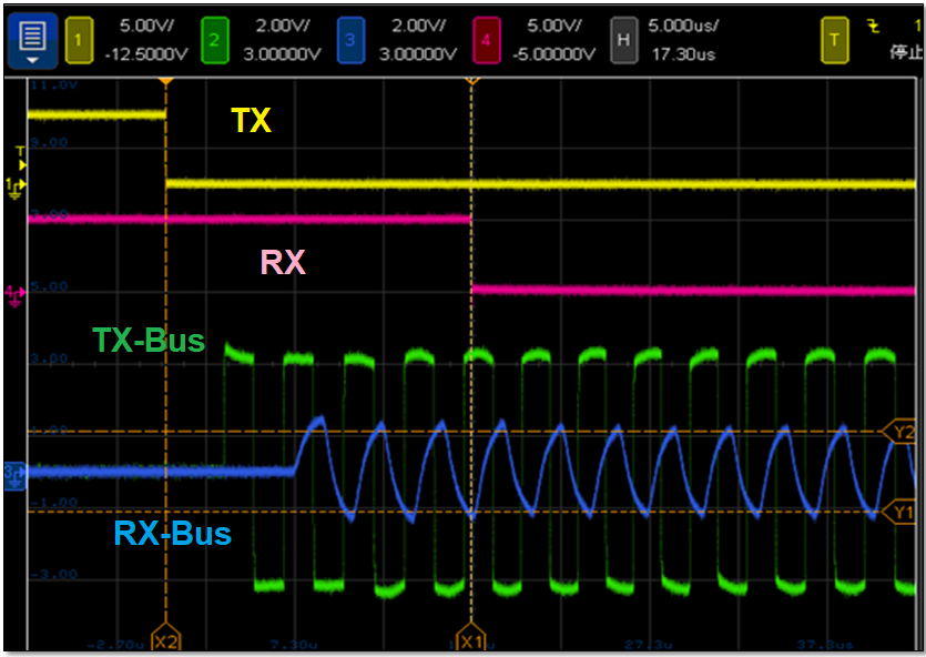
I suggest debugging starts from the DC power (case 3 - battery) first. You could also start with no power delivery and just check the data communication. It looks like the high frequency signal passes while the DC level fluctuates at the receiver side. Are the TP2 waveforms differential signal or single-ended? The cable loss of 2m should be small. Are both node 1 and 2 are powered by DCDC? Is it possible to check the supply voltage? I copy some 'normal' waveforms for your reference.
Regards,
Hao
Hi,
1. the TP2 waveforms differential signal.
2. Both node 1 and 2 are powered by DC-DC, same PCBA ,
3. the line voltage is 20Vdc, DC-DC, to THVD8010, supply voltage is 3.34V,
4. we have 4 same PCBAs , all waveform is same. and result.
we will change the lnductance value , position. Hope 'normal' waveforms appeared on different Power.
Thinks
Again, you can start by disconnecting the inductor (no power delivery). Please check the bus signal with respect to the local ground of each node.
Regards,
Hao
Hi,
we got the signal on TP3, Our opinion is between 2- line cable the smaller the capacitance, the better . when main DC power(has big capacitor) ,needs bigger inductor.
It is a problem,inductance value and high current.
Thanks.
The inductor value depends on the carrier frequency. The purpose of applying inductor is to generate high impedance to shield the data signal. Therefore the higher carrier frequency, the equivalent impedance is higher. The impedance of 330uH is about 621Ohm at 300kHz. However the inductor's current rating needs to be high enough to carry the current, which will affect the physical size.
Regards,
Hao