This thread has been locked.

If you have a related question, please click the "Ask a related question" button in the top right corner. The newly created question will be automatically linked to this question.

TPS65988EVM: FTDI Programmer Card

Part Number: TPS65988EVM

I know this is a stupid question, but, here it goes:

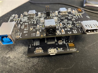
1.  Is the FTDI board part of the TPS65988EVM is suppose to be broken off and plugged to the bottom of the main board for programming and debugging?   From another post show this:

2.  If this is the case, do you have documentation on how to connect the boards.   One has a 2x12 pin socket header (main board) and the FTDI has a 2x10 pin header.   

Please advise..   

  • Hello,

    Not a stupid question at all!

    1. The board can be broken off and plugged in to access the signals. You can also leave it attached as the signals are routed through the parts where the boards are joined.  

    2. The FTDI board should plug into the TPS65988EVM by putting the top most pins together and facing the microB connector to the top. The TPS65988EVM will have extra unused plug ins at the bottom. If you attach a photo I can verify your connection. 

    Thanks,

    Emma

  • Thank you for the quick response..    This is how I did it.  I  though they would be routed but wasn't 100% sure.   My configuration changes wasn't making my device work as I was expecting so I questioned the build files (gerber) and broke it apart.     There wasn't any documentation in the manual so it would be nice to add a blurb in rev c of the manual.  

    Haven't hooked it up yet, but the ground signal ohms out between top & bottom.  

  • Looks great! You have it hooked up correctly. 

    Thanks,

    Emma