Other Parts Discussed in Thread: DPS-DONGLE-EVM, DS125DF111
Hi, there
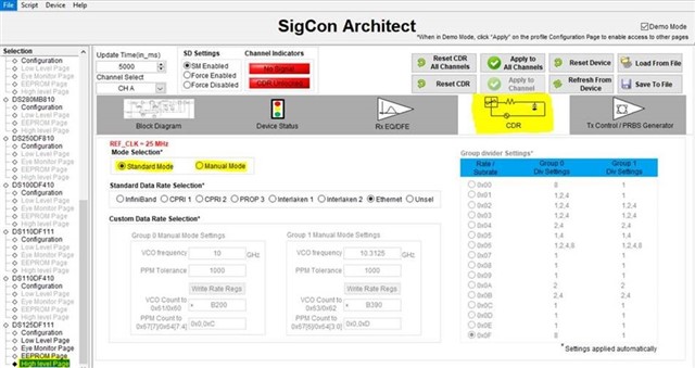
I got new purchased DS125DF111EVM board and the initial set up is as shown below

It was set as SMBus slave mode connected with DPS-DONGLE-EVM.
The INA+ was connected with 10Gbps PRBS data Vpp=300mV. The OUTA+ was connected to the oscilloscope.
At the beginning, when Vin=+3.3V, current Iin is around 24-25 mA. There is no signal detected. Could you suggest how should I set the "register" on "low level page" to make it work? or I could leave it as default?
I read the docs on https://www.ti.com/product/DS125DF111 , still have no clue. sorry I am very new to FPGA.
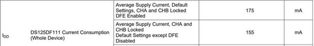
then after a while, the current jumped over 300 mA. I read from data sheet that "Maximum Transient Supply Current Default Settings: CHA and CHB " can go up to 294 mA when valid input signal detected.
but still I think the curret is too high. now even when Vin=0.1V, the curret Iin is 79 mA which is way higher than before.
Could you please advise
1. what is the proper set up of "regieter" to detect the phase lock the 10Gbps data?
2. what is the normal operating current when Vin=3.3V?
Thanks alot
Regards
Jim