This thread has been locked.

If you have a related question, please click the "Ask a related question" button in the top right corner. The newly created question will be automatically linked to this question.

SN65HVD230: SN65HVD230 sometimes works, sometimes not

Part Number: SN65HVD230

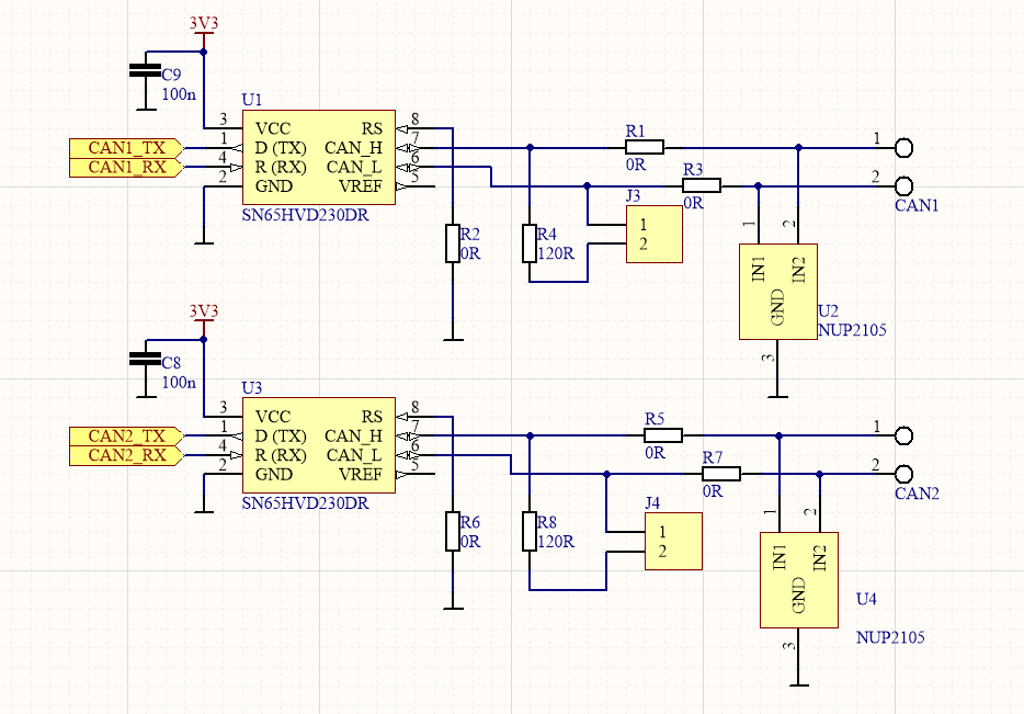
I have two SN65HVD230 devices on my board connected with wire loop about 30cm.

These devices sometimes work, sometimes not, transmiting is working, but RX is empty

What can cause this issue ?

Here is my deign:

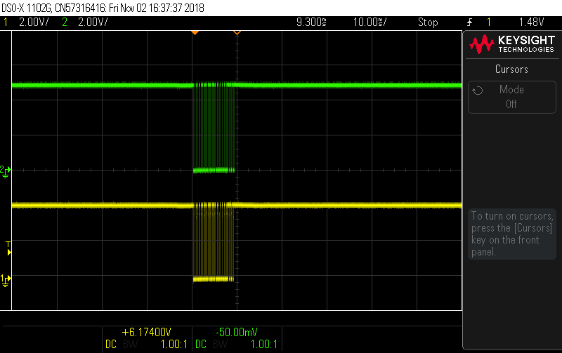
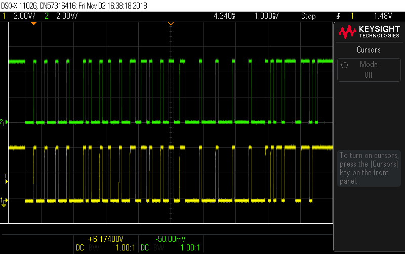
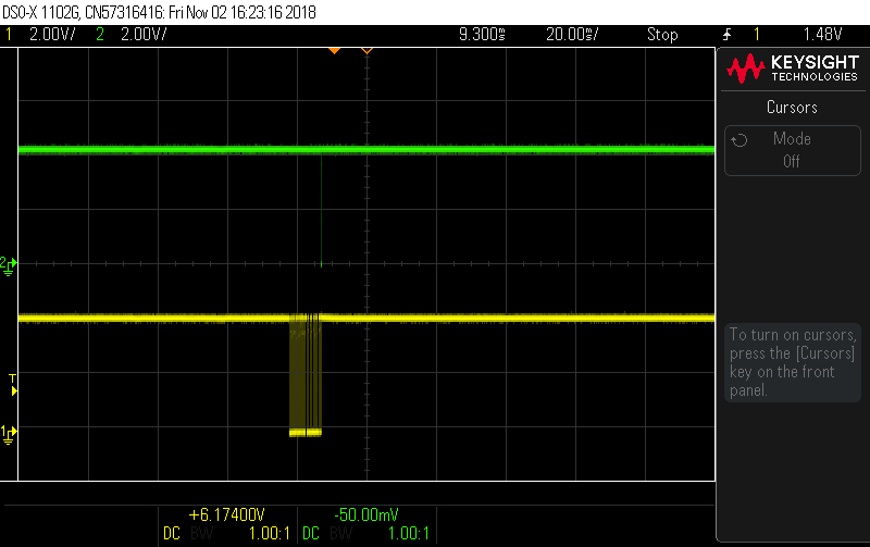
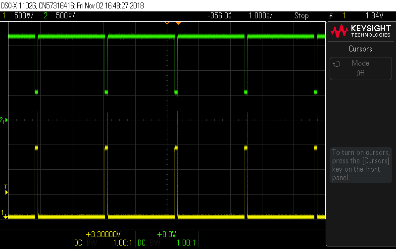
Here is my oscilograms, probe is connected beetween:

1. TX on U3(yellow) and on RX on U1(green)

2. TX on U3(yellow) and CANH on U1(green)

3. CANL(yellow) and CANH(green)

When device is working correctly.

and when device is not working:  no RX signal on U1(green), but the others signals are correct. 

  • TJ,

    It's strange that everything looks the same in both groups of screenshots except for the RXD pin. Is there any way the CANH waveforms can be zoomed in on to see the dominant-to-recessive ringing? And where exactly on the schematic are the CANH and CANL signals being probed? Does the U1 RXD respond if the U1 TXD is toggled?

    Regards,
  • Hi Eric,
    CANH and CANL are probed on CAN1 terminal block connector. Yes, I will make zoom. Do I understand correctly? Connect probes to CANH and CANL directly on pins 6 - 7 and make zoom ?
    Can the power supply cause this problem? I connected an additional 100n capacitor directly on the power pins and it seems that it is even worse.
  • TJ,

    Thanks for the information. Is there any way the CANH and CANL can be probed at the pins when it's not working? Also is there a particular pattern when it does not work vs. when it does? That's correct about the zoomed in image as well.

    If an undervoltage is triggered it could make some of the functions of the device not work, but if the RXD isn't working I would expect the TXD not to work and toggle the bus as well. I also noticed that the RXD voltage is low in the non-working case. Can you probe VCC while it's not working?

    Regards,
  • Hi Eric,

    Power suplly is stable, I have 47uF and 2x100nF.

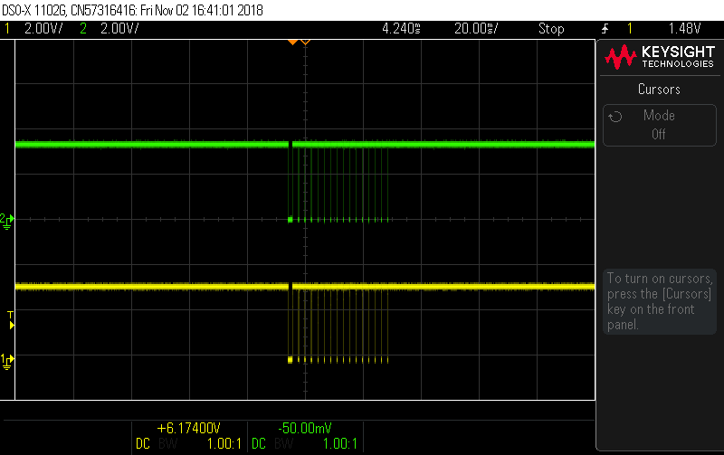
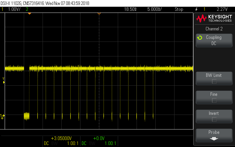
    I have second board with 5V CAN drivers, on this board CAN transmission works correctly. The same pcb and program code. CAN frame took 9.3ms. My correct transmission on U1 pins RX and TX look like:

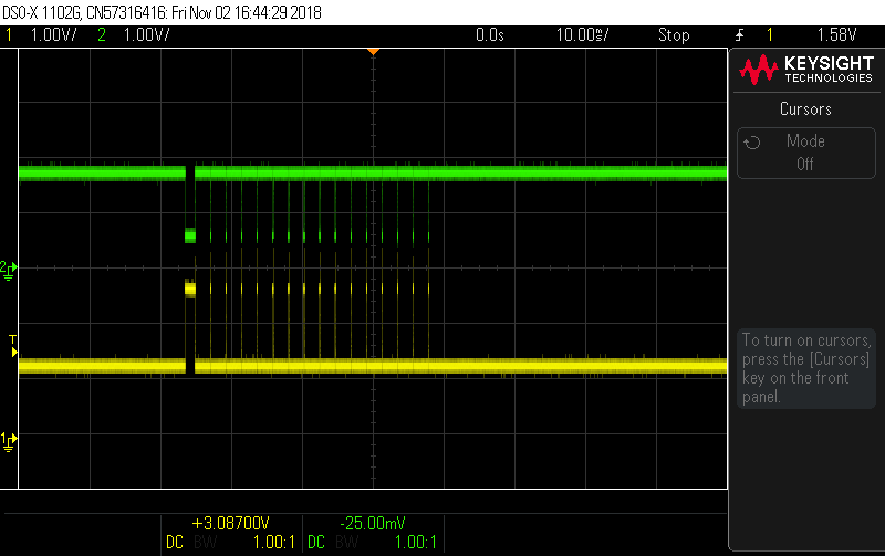
    and on receiver RX, TX pins on U3

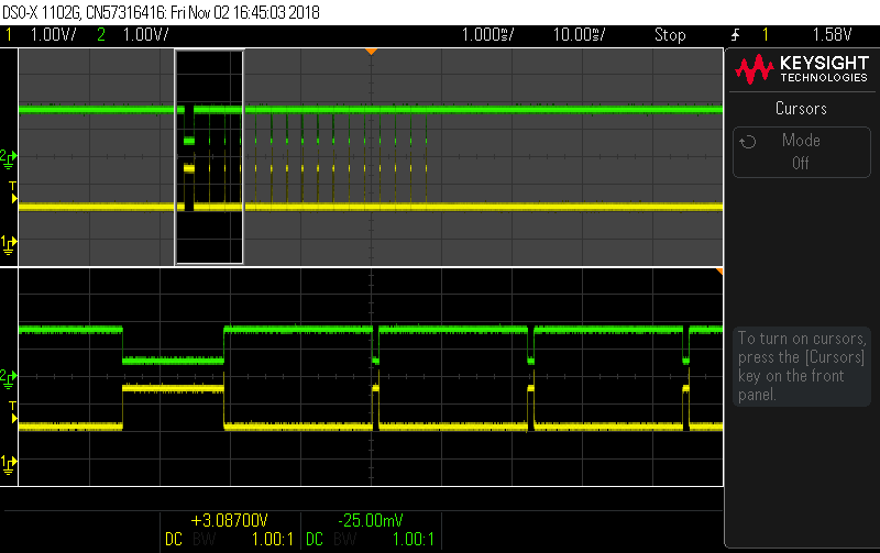
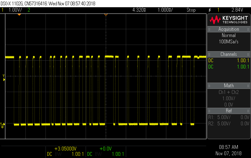
    On board with SN65HVD230 I have found different wave, Single frame take 35ms(!) and look like:

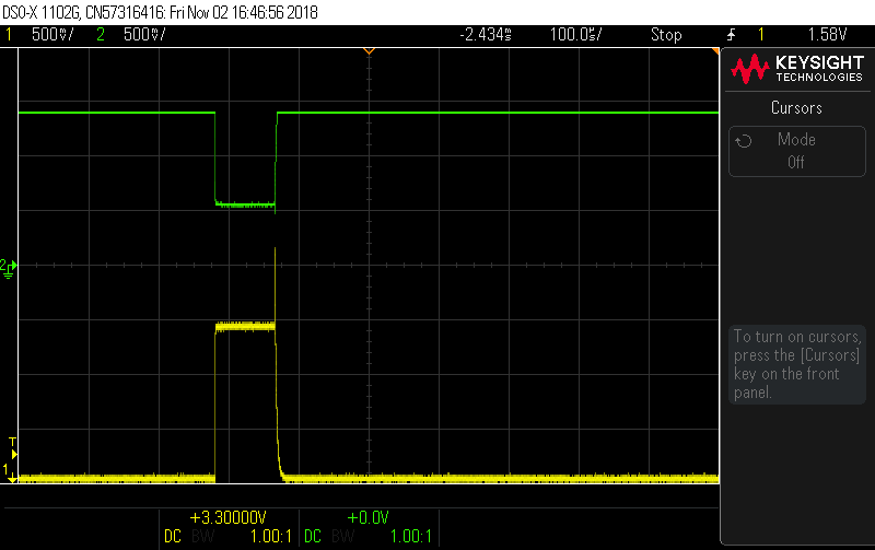
    and here is CANH and CANL directly on pins U1

    Could you explain this behaviour ?

  • TJ,

    Correct me if I'm wrong but it looks like these SN65HVD230s are working in these screenshots, besides the extended frame length, but this is completely influenced by the controller, the SN65HVD230 transceiver shouldn't have any affect on the actual frame length of the CAN message. Are you sending the exact same message in both examples above? It looks like the messages are completely different, and I would expect bit stuffing to occur if the controller was functioning correctly.

    There is still significant overshoot on the dominant-to-recessive edge though on CANH, and the CANH signal is significantly larger than the CANL signal, which I would expect the opposite with these devices.

    When probing the CANH and CANL signals, is it possible to use a math function on the oscilloscope to get the CANH-CANL value? I want to see what the differential voltage in the case where the devices are working, and when they are not working.

    Regards,
  • Yes, both pcb have exactly the same program. I have erased and program again with the same hex file. This is the most interesting.

    I have disconected RX pin from microcontroller and CANH/CANL cable, only TX pin 1 is connected.

    Here is scope on TX pin, takes 35ms and have glitches.

    And this is second board with 5V NXP tranceiver, looks good and takes 10ms

    How can this be explained?

  • TJ,

    It's clear that the controller is transmitting something different than what is being programmed in the 3.3V case, these screenshots are from the first attempt at transmitting the frame, correct?

    Even if the bus communication were working correctly, the message frame is completely different between the TI device and the NXP device. In the 3.3V case, this almost looks like the controller is going into error-passive state and transmitting passive error flags, though that would imply that the error counter is already > 127, and if this is a transmission on a fresh power up, that doesn't make sense.

    Is there any way to check the error state of the controller? And what frequency are these messages being sent?

    I need to think about this a bit more and will come back with some other questions.

    Regards,
  • TJ,

    Just wanted to check back in, I don't have any further questions. Were you able to get any of the data I mentioned in my last post?

    Regards,