This thread has been locked.

If you have a related question, please click the "Ask a related question" button in the top right corner. The newly created question will be automatically linked to this question.

SN65DSI83: SN65DSI83 has no LVDS output

Part Number: SN65DSI83
Other Parts Discussed in Thread: DSI-TUNER

                                      picture 1

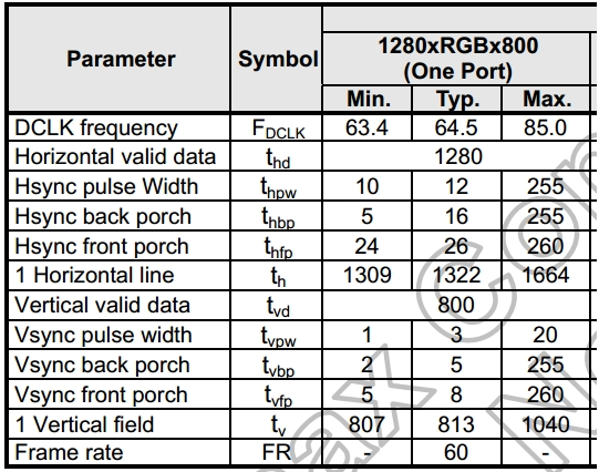
The picture 1 is the Lvds panel SPC.


                                                       picture 2

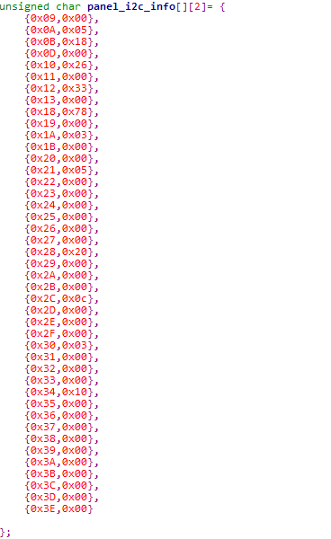
The picture2 is CSR setting.

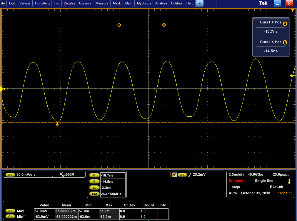
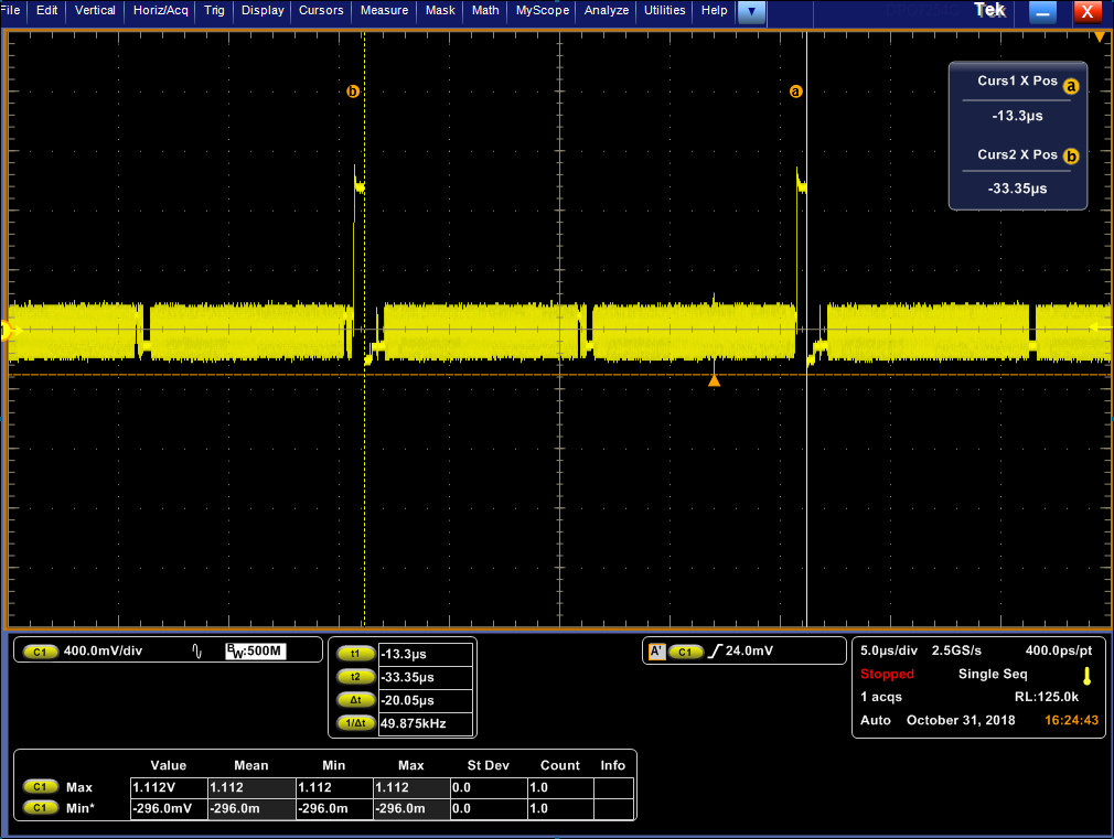
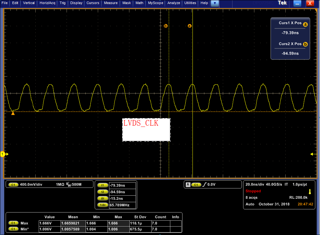
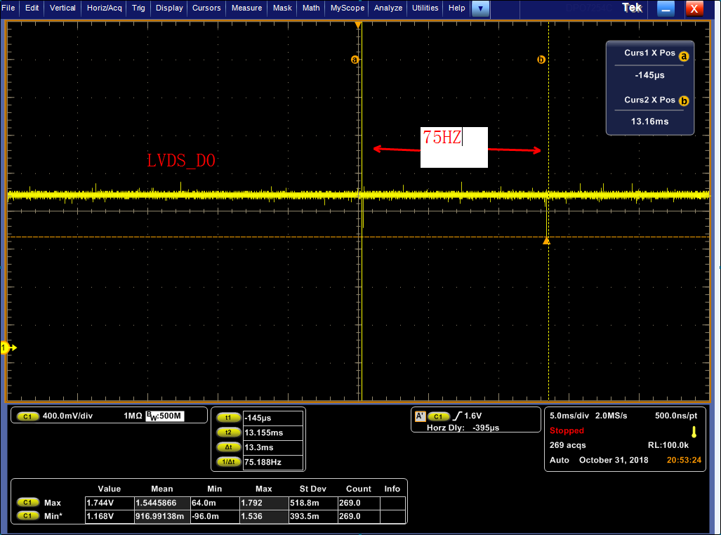
TEST result:

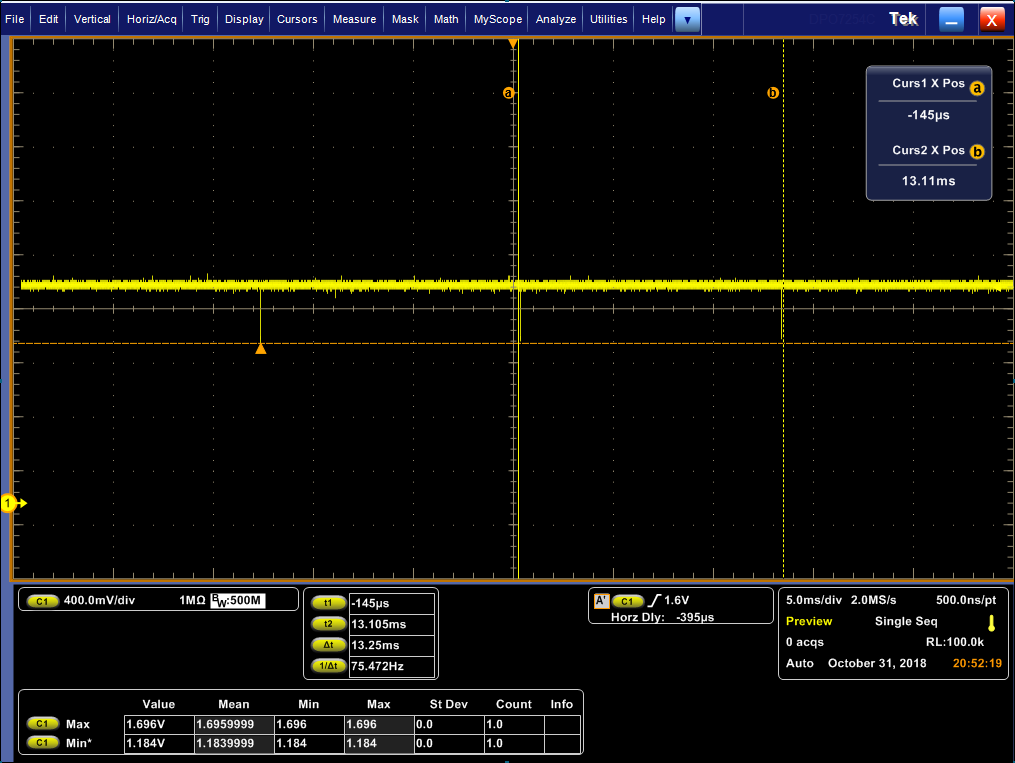
1、MIPI CLK

2、MIPI_DATA

3、LVDS OUT :CLK

4、LVDS OUT:D0

LVDS OUT: D1/D3

LVDS OUT :D2

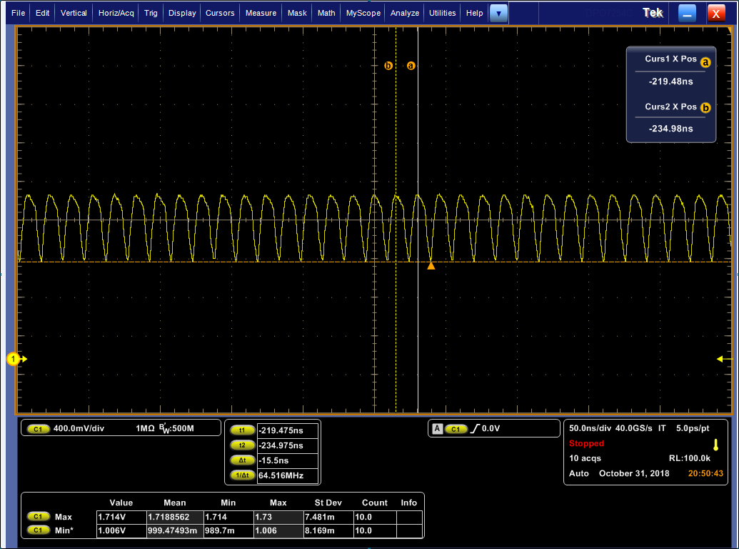
USE tuner tool test pattern :

LVDS OUT:CLK

LVDS_D0

LVDS_D1

LVDS_D2

LVDS_D3

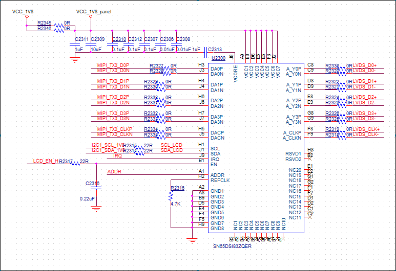
Circuit diagram:

Question:

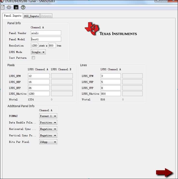
1、The tuner tool setting is OK?

2、LVDS out is NG,why,help me。What can I check?

3、IN Test pattern mode,the LVDS  is OK?

4、Can you provide me with a usable setting according to my  LCD specification.

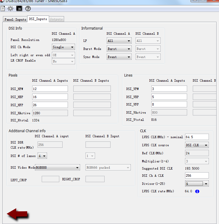
  • The picture above is Tuner setting。

    The LCD SPEC:

  • Hi Goff,

    Please use 193.5MHz as the frequency for your DSI CLK, and change the divisor value to 3. Other than that your settings look okay.

    Additionally, please ensure that you're following the initialization sequence in the datasheet.

    You can watch this video and reference this application note for additional debugging steps:
    www.youtube.com/watch
    www.ti.com/.../slla356.pdf

    Regards,
    I.K.
  • HI I.K.

    Thank you very much for your suggestion. I will check and confirm according to your suggestion

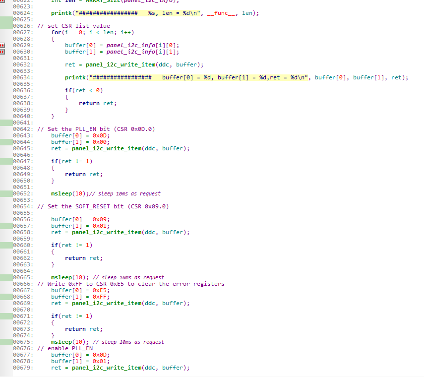
    Here's my initialization code。

    CSR CODE:

    In addition, could you provide me with a working code for my reference.

    I want to check the test pattern ,but  in test mode, From the above picture, we can see that the waveform of LVDS data is abnormall。Can you give me a setting for test pattern?For example, give me a picture of tuner tool‘s setting

    Thank you very much!

  • Hi Goff,

    Sorry but I'm not able to help you with your code.

    The initialization sequence you need to follow is listed in the datasheet:

    This is required for correct operation of the device, so you'll need to make sure that you're implementing it correctly.

    You can configure the device for the test pattern with the DSI-Tuner tool. In your screenshots of the tool, you just need to check the box next to "Test Pattern" on the Panel Inputs window. You can then generate the register settings.

    Note that the initialization sequence still needs to be followed even with the test pattern.

    Regards,

    I.K.