This thread has been locked.

If you have a related question, please click the "Ask a related question" button in the top right corner. The newly created question will be automatically linked to this question.

ISO7341C: layout considerations

Part Number: ISO7341C

Hello,

We are using the ISO7341C for RS485 isolation.

Due to layout constraints I routed the DE, TXD and RXD at the bottom layer just beneath the ISO7341C, as it can be seen from the picture:

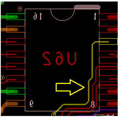
I guess that that this route can decrease the isolation capability. But since I need the isolation as functional isolation, against ground loops, I'm not concerned from this.

What I want to know is, can this route change the functionality of the  ISO7341C? Can it cause a problem with something else?

And just for my knowledge, can it decrease the isolation capability?

Thanks for your help,

Asaf Abraham

  • Hi Asaf,

    Thank you for posting to E2E! Since routing traces, vias, or copper planes underneath isolation devices can compromise the isolation barrier, we normally do not recommend it. Depending on the functional isolation requirements of your system, this may be okay, so please ensure to test the isolation performance accordingly.

    Regarding device functionality, the ISO7341C should operate normally without any problems or changes in device-level performance whether signals are routed underneath it or not. The electrical, timing, and isolation specs of the device will remain the same, however the system itself may have reduced isolation performance because of the reduced width of the isolation barrier (also known as creepage/clearance).

    The isolation specs of the isolator apply to the system when the isolator is the shortest path across the isolation barrier measured from pins on one side of the device to pins on the other side, specified by the CLR and CPG specs in its datasheet. When signals, vias, or planes shorten the distance across the isolation barrier from these values, the maximum isolation voltage ratings may decrease, especially if copper is exposed on the top or bottom surfaces of the PCB. The amount the isolation performance changes by varies based on the isolation parameter in question, the industry standard specifying the rating, and the shortest distance between conductive materials in the isolation barrier.

    I hope this answers your questions.


    Respectfully,
    Manuel Chavez

  • Hi Manuel,

    Thanks for your detailed answer.

    It help a lot.

    Best regards,

    Asaf