This thread has been locked.

If you have a related question, please click the "Ask a related question" button in the top right corner. The newly created question will be automatically linked to this question.

ISO1452: half-duplex application schematic review

Part Number: ISO1452
Other Parts Discussed in Thread: ISO1450, THVD1452

Hi Sir,

Attached file is schematic of ISO1452.

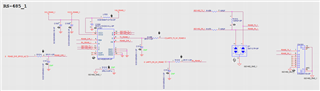
Please help to review the schmatic for RS485 half-duplex on ISO1452.

Thanks.

RS485_half-duplex.pdf

  • Hi Lee,

    Thanks for sharing the schematic of ISO1452 for review. The schematic looks good and I had a few comments / suggestions, please see my inputs below.

    1. ISO1452 is a full-duplex device, if your requirement is only half-duplex then you can consider using ISO1450 which is a half-duplex device.
    2. The full-duplex device ISO1452 can also be used in half-duplex but for that, you will have to short Y/Z to A/B for the device to operate as half-duplex.
    3. Devices ISO1450 and ISO1452 support datarates of upto 50Mbps. If your requirement is only 500kbps or 12Mbps, then you can consider using ISO143x or ISO141x, please see below table for the list of devices from this family.
    4. The existing decoupling capacitors values look good. Additionally, we recommend that a 0.1µF capacitor is added to both VCC pins. Alternatively, the 1µF cap can be replaced with a 0.1µF cap.
    5. I didn't see any termination resistor on the RS-485 bus, each node doesn't require termination resistor and it is only required at the two nodes on the opposite ends of RS-485 bus. I hope you are taking care of this in your overall system.
    6. The TVS diodes used on RS-485 bus seem to be 5V ESD diodes which are not compatible with RS-485 bus. The RS-485 bus requires a bidirectional TVS diode with working voltages of -7V and +12V. One of the suitable TVS diodes for RS-485 bus is SM712 which has working voltages of -7V and +12V and is specifically meant for RS-485 bus protection.

    Let me know if you have any questions, thanks.


    Regards,
    Koteshwar Rao

  • Hi Koteshwar,

    Thanks for your reply.
    I updated the schematic.

    Actually, the original design plan for full-duplex application but the four line UART not enough now.

    We will evaluate the others function or change the ISO1452.

    reply as below:

    item2=>May I know, short Y/Z to A/B means Y short to A and Z short to B?

    item4=>our database rule D=0, so SCD1U10V2KX-4-LL-GP is 0.1u/10V/0402, I need modify it anymore?

    item5=>Do you mean "at the two nodes on the opposite ends of RS-485 bus" is the 120R for TX to connect RX?

    item6=>updated to schematic

    Thanks.

    RS485_half-duplex_221011.pdf

  • Hi Lee,

    Thanks for the updated schematic. I see that you have connected Y/Z to A/B lines to form half-duplex configuration which looks good. I also see you have included termination resistor and updated the TVS diode which also look good.

    item2=>May I know, short Y/Z to A/B means Y short to A and Z short to B?

    Your understanding is correct, the schematic is also updated correctly.

    item4=>our database rule D=0, so SCD1U10V2KX-4-LL-GP is 0.1u/10V/0402, I need modify it anymore?

    Sorry, I couldn't find the datasheet for capacitors. From the part numbers, it looked like SCD1U10V2KX-4-LL-GP is 1µF and SC10U16V5KX-19-GP as 10µF. But if SCD1U10V2KX-4-LL-GP is 0.1µF then that's good.

    item5=>Do you mean "at the two nodes on the opposite ends of RS-485 bus" is the 120R for TX to connect RX?

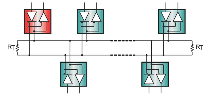
    Yes, the RS-485 bus requires 120Ω termination resistor used at the opposite ends of the bus. Only 2 resistors for one RS-485 bus, as shown below. Thanks.


    Regards,
    Koteshwar Rao

  • Hi Koteshwar,

    Thanks for your review and explain.

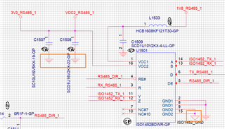
    I want to confirm about isolated GND, below the drawing not same as datasheet.

    The GND2 could be changed to left GND (system GND) for VCC2 reference?or other suggeston?

    Thanks.

  • Hi Lee,

    Sorry, I missed to notice the GND symbol being different for capacitors C1507 and C1508. Please note that if your application requires isolation then you can only maintain isolation by keeping the power and signal lines on left and right side isolated from each other. Signal isolation is achieved ISO1452 while power isolation is achieved by using isolated power. Please refer to the below links for more details on this topic.

    How to Isolate Signal and Power for an RS-485 System (Rev. C)

    You can find more application notes and other useful documents on the ISO1452 product page, please see the link below.

    https://www.ti.com/product/ISO1450#tech-docs


    Regards,
    Koteshwar Rao

  • Hi Koteshwar ,

    If we don't concern the isolation, can I modify the GND as below?

    Thanks

  • Hi Lee,

    You can connect both GND1 and GND2 to the same system ground and the device will still work but the isolation barrier in the device will not be. If isolation is not a requirement and you only need an RS-485 transceiver, then you can just use an RS-485 transceiver instead of isolated RS-485 transceiver, these are going to be cheaper and you will also have more options to choose from. I am copying below the link to THVD1452 which is an RS-485 transceiver and doesn't include isolation.

    https://www.ti.com/product/THVD1452

    Let me know if you have any further questions, thanks.


    Regards,
    Koteshwar Rao

  • Hi Koteshwar,

    I got it.

    The THVD1452 just transceiver hasn't isolation function and cheaper.

    My system have 2 RS485 but they are connection to Soc by oneself so THVD1452 and ISO1452 should be apply on our system?
    Thanks.

  • Hi Lee,

    Yes, both THVD1452 and ISO1452 can be connected to SoC independently forming two RS-485 interfaces, one without isolation and the other with isolation. If you like to maintain isolation with the ISO1452, then you should keep the power supply connections also isolated by using an isolated power supply. I share you a few documents in my previous showing how to achieve RS-485 isolation. Those should help you as a reference.

    If isolation is not a requirement and if you would like to use two RS-485 interfaces connected to the SoC, then you can also consider using two THVD1452 devices.

    Let me know if this answers your questions and if I can go ahead and mark this post as closed. Thanks.


    Regards,
    Koteshwar Rao

  • Hi Koteshwar,

    very clear.

    Thank you very much.