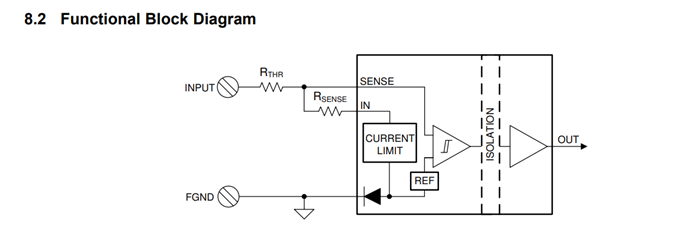
I need some help understanding the behavior shown in Figure 29 (sourcing/sinking inputs).
The diagram seems to show an AC input waveform, but is it safe to assume the same configuration works for DC as well?
Also, from the ABS MAX values in Section 7.1 of the datasheet I see VINx / VSENSEx is ±60V.
From this I understand using the reverse-connections shown in Figure 29 are safe.
I understand then the SENSE pin can see current flow in both directions.
Are there any key concerns here to be aware of?