ISOW1432: What is the maximum CMVR?

Part Number: ISOW1432

Tool/software:

Hello Team,

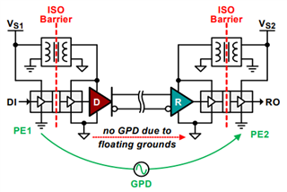
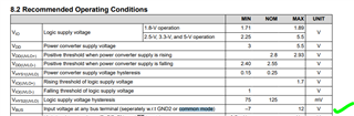
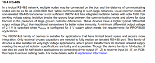
From the datasheet of  ISOW1432 it is shown that -7V to 12V is the CMVR. But for non isolated transceivers also has the same range. I hope this value is not the correct value

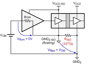
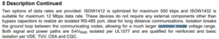
From the below mentioned information the common mode voltage range should be greater than the above mentioned table. If you have tested this IC for CMVR please share the maximum CMVR for this IC. And also request you to share the required test methodology to test CMVR for this IC. 

If you have any testing procedures for CMVR please share. We need the actual value of CMVR for this IC .

Thanks,

Srikanth K

  • You are supposed to connect GND2 to the RS-485 ground line.

    You get a wider CMVR relative to GND1.

  • Yes i understood wider range but what is that value is my doubt

  • WIOWM (DC) is specified as 1500 V.

  • is this CMVR(AC/DC) for error less communication? 

    For example:

    If I apply 1500V DC/AC across GND2 and RS-485 ground line then data has to receive at MCU side with out any errors

  • This value is for DC offsets; AC is 1000 V. (The test details are specified in DIN VDE V 0884-11:2017-01).

    The common-mode transient immunity is specified in section 8.8 as 100 kV/µs.

  • Hi Srikanth,

    Thank you for reaching out.

    As Clemens stated, the RS-485 bus common-mode voltage supported by device without respect to GND2 is -7V to 12V. But the separation / isolation of GND1 and GND2 breaks the ground-loop across RS-485 nodes. In this case, the common-mode voltage would be the same as the isolation working voltage which is 1000Vrms or ±1500VDC. Let me know if this answers your question, thanks.


    Regards,
    Koteshwar Rao

  • Thank you very much for your clear explanation. 

    I remember the same kind of explanation I have read through www.edn.com/.../

    Below is the equivalent circuit of what you explained

    From this equivalent circuit "Figure 4 clarifies the situation by providing the common-mode equivalent circuit of the isolated receiver node. Because the huge resistance of the isolation barrier (RISO = 1014 Ω) is in series with the receiver’s much lower common-mode resistance (RCM = 105 Ω), the entire VCM drops across RISO , thus eliminating the common-mode impact across the receiver (VRcm = 0V). Additionally, the GND2-ISO potential tracks the receiver input voltage, so there is no worry about violating the receiver’s maximum input voltage relative to the receiver ground."

    But I could not able to understanding that after ground got isolated how the Vcm is dropping across Riso.

    Could you please explain in a simple terms.

    Thanks,

    srikanth k

  • Hi Srikanth,

    The diagram and paragraph you have shared are accurate and explained very well. Since RISO is much larger than RCM, most of the VCM will appear across RISO. This is the only reason why VCM appears across RISO. Thanks.


    Regards,
    Koteshwar Rao

  • Hello Koteswar Rao,

    In continuation to the previous conversation, I have planned to test the VCM by implanting 230Vrms GPD across the source and receiver as shown below. Kindly suggest if there is any detail document on the same.

    We planned to use Vs1 and Vs2 to source with separate transformers and GPD with separate transformer. Hope this wont be an issue.

    Thanks,

    Srikanth K

  • Hi Srikanth,

    Thank you for following up with additional questions.

    The difference between PE1 and PE2, referred as Ground Potential Difference (GPD), is typically in 10s of volts which is much lower than 230Vrms. But we do not expect any issues when tested with 230Vrms, please go ahead and test with 230Vrms between PE1 and PE2 and let me know if you have any questions.

    Vs1 and Vs2 can be independent power supplies powering the two devices in diagram, this is expected and perfectly fine. Thanks.


    Regards,
    Koteshwar Rao