This thread has been locked.

If you have a related question, please click the "Ask a related question" button in the top right corner. The newly created question will be automatically linked to this question.

ISO35T: Operation when Vcc1 is off and RS-485 side is Active

Part Number: ISO35T
Other Parts Discussed in Thread: ISO1430, ISO1410

Hello

My customer is using ISO 35T in the following circuit.
Primary Side is powered off.
RS-485 side is active and 1.2VDC is applied to Y and Z.
At this time, 0.5V is observed at the Vcc2 terminal.
・ Why is 0.5V generated?
・ Is ISO35T not working even if 0.5V is applied to Vcc2?


Best Regards,

Kaede Kudo

  • Kudo -san,

    The 0.5V you are seeing on Vcc2 is most likely due to an internal protection diode on the bus lines that is connected to Vcc2. The voltage drop across a diode is roughly 0.7V.

    1.2V - 0.7V = 0.5V

    Does the ISO35T continue to function if powered on after the 1.2V is introduced? Is the 1.2V biasing on the bus lines for fail safe? Also, we have much newer products than the ISO35T. A combination of the ISO1410 or the ISO1430 with the SN6505 could be a stronger solution than the ISO35T.

    Respectfully,

    Lucas Schulte

  • Hello Lucas-san,

    Thank you for your fast reply.
    I appreciate your cooperation!

    If a protective diode is included, the description of absolute maximum rating will be described as Vcc + xxV.
    The description of ISO35T is an absolute value.
    Why is this?

    Even if a voltage of about 0.5 V is generated on VCC2, does ISO35T not work?
    Customers expect to not work.

    Best Regards,

    Kaede Kudo

  • Kudo -san,

    The ISO35T should not turn on from 0.5V. This is below the under-voltage threshold of the device. This should meet the customer's expectations. We can do further analysis as to why 0.5V appears on Vcc2 in the lab.

    Respectfully,

    Lucas

  • Lucas-san,

    Thank you for your comment.

    I will wait for your feedback.

    Best Regards,

    Kaede Kudo

  • Lucas-san,

    I have one more question.
    What is the value of UVLO?

    Best Regards,

    Kaede Kudo

  • Hello,

    Are there any updates?

    Best Regards,

    Kaede Kudo

  • Hi Kudo-san,

    I am Manuel, on the Isolation team with Lucas. UVLO for the ISO35T is between 2V - 3V. A sample unit measured at 2.55V


    Thank you,
    Manuel Chavez

  • Hi Manuel-san,

    Thank you for your reply!
    I understood UVLO of ISO35T is between 2V - 3V.

    Best Regards, 


    Kaede Kudo

  • Hello,

    Is there any progress on the above inquiries?

    Best Regards,

    Kaede Kudo

  • Hi Kudo-san,

    I apologize for the delayed response. Are you asking for an update regarding the 0.5V that appear on our customer's Vcc2 pin? If so, can you share whether there is activity on the ISO35T's A and B lines? An internal connection might be made to Vcc2 from the RS-485 bus.

    I will await your response.


    Thank you,
    Manuel Chavez

  • Hi Manuel-san,

    Thank you for your reply,

    I am confirming with the customer that I was asked the question now.

    Please wait until the answer.

    Thank you for your cooperation!

    Best Regards,

    Kaede Kudo

  • Kudo-san,

    Okay! Please do let us know. If there is no response in ~1 week, this thread will be closed due to inactivity. At that point, a new or related thread may be started by asking a question using the red and yellow buttons in the top right of this window.


    Thank you for your time,
    Manuel Chavez

  • Hi Manuel-san,

    Thank you for your cooperation!

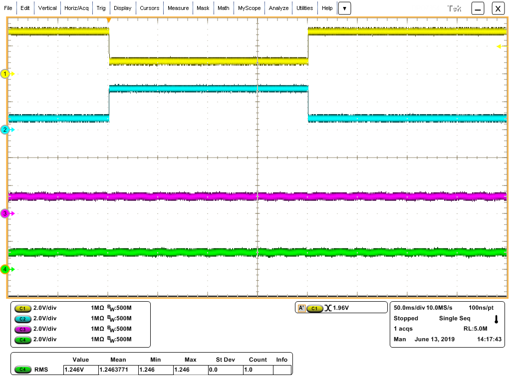
    I received a response from my customer, so I will expand it.

    - ch1(yellow): A, High 3V, Low 1V
    - ch2(blue): B, High 3V, Low 1V
    - ch3(pink): Y, 1.2VDC
    - ch4(green): Z, 1.2VDC 


    Is this information sufficient to solve the problem?
    Please tell us if there is any missing data.

    Best Regards,

    Kaede Kudo

  • Hi Kudo-san,

    Thank you for these values and oscilloscope image. From the data given and lab testing on our end, it is determined that the the 0.5V on Vcc2 is caused by a high impedance leakage path which does not supply enough current to charge Vcc2 to UVLO+ and will not  turn the device on.


    Thank you for posting to E2E!
    Manuel Chavez

  • Hi Manuel-san,

    Thank you for your reply!

    I developed your answers to my customers.
    Thank you for your cooperation

    I have a question from my customer, so I'm sorry but could you just keep going?

    Their questions are as follows.
    1. Please tell me about the high impedance leakage path at the block diagram level.
    2. Is the power supply voltage generated on Vcc2 higher by 0.5V or more?

    Best Regards,

    Kaede Kudo

  • Hi Kudo-san,

    No worries!

    Regarding our customer's questions, there is not more I can say about the leakage path other than it is very high impedance and limits the current to the order of µA on each pin (5µA from our lab tests). This current is very low and not enough to turn the device on.

    During device operation, voltage on Vcc2 should not shift or increase by 0.5V or more.


    Thank you,
    Manuel Chavez

  • Hi Manuel-san,

    Thank you for your cooperation!

    I understood as follows.
    -There is no block diagram showing the path of Leakage Path.
    However, the current of Leakage Path never turns on the power of Device.
    • When the customer uses the above method, Vcc2 does not generate more than 0.5V.

    Thank you for your cooperation.

    Best Regards,

    Kaede Kudo