This thread has been locked.

If you have a related question, please click the "Ask a related question" button in the top right corner. The newly created question will be automatically linked to this question.

ISOW7821: Having Noise on input VCC

Part Number: ISOW7821

Hello,

I am trying to use ISOW7821DWER in one of my design, I have connected Input VCC as 3.3v and expect output also as 3.3V but there are two problems:

1. I see a lot of noise introduced to VCC(3.3v) as I connect it to VCC of ISOW7821DWER.(random noise on 3.3V, 500mV peak to peak.

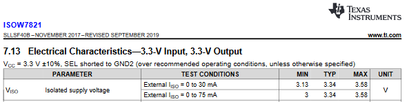
2. Output side(after isolation) I don't get regulated 3.3v but it is like 3.66V, I will I tried putting a 1K resistance as dummy load but it doesn't come down. I will be connected to a metering chip over the UART connection and that will not take more than a few milliamps so I am concerned how can I get ~3.3v output VCC.

I tried putting SEL pin to GND_ISO_1 as well but nothing changes.

Best Regards

Pallav Aggarwal

  • Hi Pallav,

    Thank you for posting, and welcome to E2E!

    Is it possible for you to test the output voltage with a bench power supply or a cleaner power supply connected to Vcc input? 3.66V on the output might be due to the 500mV noise -- as shown in the ISOW7821 datasheet clipping below, Viso is not expected to exceed 3.58V during 3.3V to 3.3V operation:


    I will await your response.


    Respectfully,
    Manuel Chavez

  • 3.3v input is coming for an LDO which is generating 3.3v from a 12V AC-DC adapter input.

    I am more concerned about input VCC generating 500mV noise as soon as I connect to ISOW7821, If I do not connect, the supply is clean.

  • Hi Pallav,

    Thank you for sharing this information. Our ISOW78xx expert will reach out to you via the email associated with you myTI account to get more information on this.


    Respectfully,
    Manuel Chavez

  • Hi Pallav,

    Sorry to hear about the issue and thanks for sharing the schematic. There can be multiple reasons for seeing higher input ripple voltage at VCC pins as listed below,

    1. If the output capacitor at the output of LDO is not sufficient.
    2. If the placement of input capacitors at VCC pin of ISOW7821 are not close to VCC pins as recommended in datasheet.
    3. If the input capacitors at VCC pin of ISOW7821 are not placed on the same side of PCB as ISOW.

    To better help you address the issue, please do share us a little broader schematic and PCB layout showing LDO as well. Please also confirm if I can reach out to you on the email that you have used to create your E2E profile. Thanks.

    Regards,
    Koteshwar Rao

  • Sure, you can contact me on my email id.

    10uF + 0.1uF are closed to ISOW7821 both input and output, are on the same side(TOP)

  • Is there any other suggestions or tests I should try?

  • Hi,

    This discussion has been moved to email. Once the discussion has been brought to conclusion, I will try to post a summary update to this post. Thanks.

    Regards,
    Koteshwar Rao

  • Hi Pallav,

    Thanks for sharing detailed schematic and PCB layout.

    After reviewing the schematic, I have provided you the below recommendations. Thanks

    1. The capacitance at the output of LDO is not sufficient to supply the requirement current to ISOW.
      1. I recommend adding either a 100µF capacitor. This is especially important because the LDO is powering 3 ISOW devices.
    2. I would also recommend increasing the input caps at all 3 ISOW from 22µF to 47µF.
    3. Since the load on ISOW VISO output is not much, please also reduce the output caps (C1, C16, C30) on VISO of all 3 ISOW from 22µF to 4.7µF.
      1. The regulation frequency of ISOW varies with load and low loads keep the frequency very low. This makes the input voltage ripple increase.
      2. Changing output cap from 22µF to 4.7µF and keeping the other 0.1µF as is, will increase the regulation frequency from <10kHz to >20kHz (which is same as the ripple voltage frequency).
      3. This increase in regulation frequency also brings down the input voltage ripple to a much lower value.

    Regards,
    Koteshwar Rao