This thread has been locked.

If you have a related question, please click the "Ask a related question" button in the top right corner. The newly created question will be automatically linked to this question.

12V Transformer driver for isolated gate drive power supply requirements

Other Parts Discussed in Thread: SN6501, LM25180, SN6505B, SN6505A

Hello

Can someone please suggest a solution for isolated power supply for a isolated gate driver IC.


Input voltage 12V
Output voltage 12V
Current = about 0.5A or less

I searched for transformer drivers and couldn't find a solution with 12V input.
SN650x series is not suitable as it is supplied from 5V.

Thank you

  • Hi Damith,

    Thank you for posting to E2E! Although TI does not currently have a version of SN6505 that supports 12V, we do recommend a configuration of these devices with HV FETs to complete an isolated push-pull power supply design, as shown below:


    Ratings of external components determine the final system specifications, but a 12V/1A power supply could be generated using FETs that have Vgs_th <<5V, Vds >24V, and minimum Rds_on. Is this a solution you would like to pursue?


    Thank you,
    Manuel Chavez

  • Hello Manuel

    Excellent. 
    This seems like the solution.
    Please be kind enough to answer the following questions as well.

    1. Since we use mosfets to drive the TF, is it ok to use the SN6501 instead of 6505 ?..
    2. Also, is it possible to drive multiple mosfet-transformer arrangements of the proposed method using a single SN650x driver.?  (to obtain multiple 12V outputs).
    3. If the above (2.) is true, then what will be the maximum number for such mosfet-transformer arrangements.
    4. Can i use the 5V,5V pushpull transformers designed for SN650x devices,  in this 12V,12V system.
    5. is there any other IC in TI besides SN650x series, which can drive from 12V?

    6.In this system, mosfet sources are connected to the driver. Is there a way to connect gates and drive the mosfets.?

    Thank you
    Damith

  • Hi Damith,

    We are glad to help! Below are responses to your questions in corresponding numbers:

    1. SN6501 can be used in place of SN6505, but it has lower current-sinking capabilities: 350mA max primary side current vs. 1A max for SN6505. In this topology, SN650x is connected in series with the FET drain and source, so it does still have to sink the load current as reflected on the primary side of the transformer.
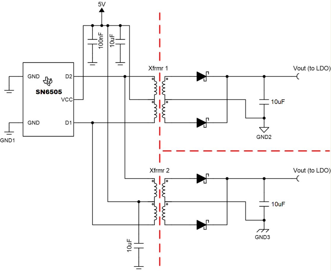
    2. Yes, this would be possible if a connection similar to the one below is followed:


      If the high voltage topology shared in my previous response is followed, the parallel transformer connections can be made on the "right" side of the HV FETs. Please let me know if you have further questions on this topology or transformer/component selection.
    3. One SN6505 or SN6501 device can support multiple connections so long as the SN650x devices' current ratings are not exceeded. This means the combined expected isolated load currents and parasitics must be within the I_D1/I_D2 specs of 1A or 350mA.
    4. This is a transformer-specific question. The turns ratio may be appropriate for 5V:5V and 12V:12V operation, but the transformer's V-t product may not be sufficient. Please share the transformer part number, and I will confirm whether it can be used for 12V:12V operation.
    5. There are other TI chips that don't use push-pull topologies to create isolated power rails like LM25180, among others. Please feel free to search for isolated power devices on TI.com, starting with this webpage.
    6. There is a way to connect the gates of these FETs to the SN650x - shown below - although some benefits of the SN6505, like current limit, thermal shutdown, and spread spectrum, are lost in this configuration:


    Please let us know of any further questions you have!


    Thank you,
    Manuel Chavez

  • Hello Manuel

    Thank you for the very good explanation

    I came into following conclusions. Please correct me if im wrong.

    Im planning to use this on mosfet gate drive power supply
    Lets say one mosfer-driver combination needs 100mA continuous current.
    Then we can connect about 9,   1:1 transformers to the SN6505B and the HVmosfets in parallel.
    Drive voltage planned is 12V.  So the calculated volt second value came as about 17.9Vus.
    In sn6505 datasheet, there is a recommended transformer which has part number 750315240.
    It is recommended for SN6505A, 3.3-3.3 and 1A. It has Vus value of 23.
    So this means, i can use this for my design with SN6505B.


    There is another question. In online sites like digiKey, they have a parameter which have inductance value at a specific frequency. How this is used to select the  suitable transformer.
    If volt second value is not given in the site, how it can be calculated from the data available.

    Thank you
    Damith

  • Hi Damith,

    You're welcome!

    The conclusions you shared are all correct regarding compatibility of 750315240 with SN6505B, the V-t product calculation, and the theoretical ability to connect 9 transformers in parallel that each contribute 100mA or less to the current SN6505B is sinking.

    When developing this configuration, test the system with each transformer individually to confirm the power consumption is as expected before combining them, and add each transformer and its isolated load one at a time to the SN6505B. This configuration has not been validated by TI.

    One advantage of push-pull power isolation topologies is their compatibility with a wide range of transformers and different inductances. V-t product and turns ratio are essential to determine whether a transformer is fit to use,  so if either is not listed on a part's datasheet, please do reach out to the transformer vendor or manufacturer and ask for this spec.


    I will be out of the office for the US holiday of Thanksgiving until Monday. Please keep this in mind, and one of my colleagues may join this conversation as needed meanwhile.


    Have a great weekend!


    Thank you,
    Manuel Chavez