This thread has been locked.

If you have a related question, please click the "Ask a related question" button in the top right corner. The newly created question will be automatically linked to this question.

ISOW7842: ISOW7842

Part Number: ISOW7842

We are using the ISOW7842 in an IOT device . We faced issue with radiated emission earlier and later we fixed with Stitching capacitor and ferrites on the VCC lines .

Currently unit is passing CISPR 25 Class A limits with good margin , Meeting class B limits with 1-2dB margin .

Since its an IOT device , unit should also meet WiFi Radiated spurious emission test . We have seen noise from the Isolator at 520Mhz and 570Mhz broadband nature .The noise is crossing the limits by 2-3dB  , Tried shielding and external capacitor between GND's , no promising results observed . 

Request you to suggest a quick fix to solve the issue . 

Is this Isolator IC passed previously for  Radiated spurious emission test in any product .  Or Is this IC  not suggested  to be used in an IOT Radio environment .

  • Hi Dilip,

    Thank you for posting to E2E and for sharing the details above. We do not expect ISOW7842 to fail radiated spurious emissions tests, however we cannot confirm whether the isolator is the source of emissions at 520MHz and 570MHz here since internal switching frequencies are lower. A quick fix if the issue is due to the isolator might be to solder a Y-Cap between GND1 and GND2 (directly onto device pins) and retest, any Y-Cap with value >100pF should reduce emissions further from isolator.

    What is the capacitance value of the stitching capacitor you have implemented? We recommend capacitance values from 30pF to >100pF where needed to reduce emissions. Please also share the ferrite part number you are using and the Vcc1 operating voltage of ISOW7842 in this system.


    Thank you,
    Manuel Chavez

  • Hi Dilip,

    Just checking in to see if you will be able to share the information requested by Manuel for us to make further suggestions in resolving your issue.

    Dilip Kumar1 said:
    Currently unit is passing CISPR 25 Class A limits with good margin , Meeting class B limits with 1-2dB margin .


    I see that you have used a stitching cap and ferrites on VCC lines to reduce radiated emissions and you already seems to pass your end equipment emissions requirement. Could you please confirm if you meant to refer CISPR 22 Class A / Class B or you indeed mean CISPR 25?

    Dilip Kumar1 said:
    Since its an IOT device , unit should also meet WiFi Radiated spurious emission test . We have seen noise from the Isolator at 520Mhz and 570Mhz broadband nature .The noise is crossing the limits by 2-3dB  , Tried shielding and external capacitor between GND's , no promising results observed . 


    Will you be able to share more details on how exactly you do WiFi radiated spurious emissions test?

    Dilip Kumar1 said:
    Is this Isolator IC passed previously for  Radiated spurious emission test in any product .  Or Is this IC  not suggested  to be used in an IOT Radio environment .


    Yes, we have seen other customers who have used ISOW device with a radio module in close-by distance on the same PCB. If the radio module is placed very close to ISOW device and on the same PCB then it is possible that WiFi module sensitivity might reduce a little bit. A sure way to improve this, is to implement a stitching cap which I see you have already done. If you provide the below requested information then I will be able to review your design and make suggestions to improve results. Please do share the below information,

    1. Schematic and PCB layout
    2. What is the value of stitching cap implemented?
      1. Min 30pF is needed to see any improvement and a min 50pF is needed to see moderate improvements
    3. Share details related to WiFi radiated spurious emissions test
      1. We have not done this test by ourselves but I believe customers who have used ISOW in their application have done such tests
    4. Details of the ferrites used

    Regards,
    Koteshwar Rao

  • Here is the Schematics and layout ,

    We have some restriction on space , so as per calculation the internal parallel plate capacitor value will come around 5pf .

    Radiated spurious emission test is asp per EN300328 standard requirement .

    We have plastic enclosure not a metal one.

  • 8585.Isolator.pptx

    Here is the design details and RSE Test limits

  • Hi Dilip,

    Thanks for sharing details as requested.

    A stitching cap of 5pF formed using internal PCB layers is too low to see much of an improvement. Please do check the possibility of achieving a higher value, at least 30pF.

    Regarding the ferrite beads (FB) used on VCC lines, the FB offers decent impedance but it is not much at the frequency where you are seeing the issue (520 - 570MHz). Since the radiations for isolators are of common-mode nature, it is important for these FBs to be used on both VCC and GND lines. Using these FBs only on VCC lines might not be effective.

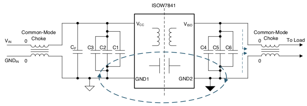
    Alternatively, a common-mode choke (CMC) can be used which offer much higher impedance for the frequencies of interest. We recommend you to use common-mode chokes (CMC) at both input and output power supply pins of ISOW as shown in the image below.

    The ferrite beads on I/O lines are optional, you can also choose to use >1kΩ resistors instead if the datarate is not very high. Please make sure all the I/O signals are referred to the GND points after the CMC and not to ISOW device GND pin. ISOW device GND & GNDISO pins should stay local to device and all the signal I/Os should only refer to the GND point that is after the CMC.

    The CMCs should have an impedance of >1kΩ at the frequencies of interest, I am listing below some of the example CMC part numbers that we recommend.

    1. CMC - 200mA, 15kΩ - TDK - ACT1210-510-2P

    2. CMC - 200mA, 20kΩ - TDK - ACT45B-510-2P

    3. CMC - 200mA, 10kΩ - Wurth - 744235510

    Since the CMCs offer significant impedance to common-mode noise, CMCs alone might be sufficient to achieve requirement improvement and a stitching cap might not be needed. Alternatively, you could as well use FBs in place of CMCs in case the improvement needed is small. The FBs to be used on both VCC and GND lines to replace the CMC.

    Please let me know if you will be able to consider these suggestions, thanks.

    Regards,
    Koteshwar Rao

  • Hi Dilip,

    I hope you have the necessary inputs from our end to address the radiated emissions issue that you are seeing in RSE test. I will go ahead and mark this thread closed. Once you implement the suggestions and test it accordingly, please do let us know your observations.

    If you have any further questions, you can just respond to this post. Thanks.

    Regards,
    Koteshwar Rao