This thread has been locked.

If you have a related question, please click the "Ask a related question" button in the top right corner. The newly created question will be automatically linked to this question.

ISOW7841: Output over-voltage protection

Part Number: ISOW7841

Hi,

In some early designs we've had an issue with over-voltage on isolated side of ISOW7841 (~7V instead of 5V), not knowing what is the cause of this.

One solution to protect the load downstream would be to use Zener diode. However I am more in favor of solution along the lines stated in the AppNote .

Would something similar work with ISOW7841 and self-correct it or should I use an optocopupler to pass the feedback signal to the primary side and re-start ISOW7841?

What is the possible cause of over-voltage and could it be prevented in the first place?

Thanks,

Goran

  • Hi Gorbal,

    Thank you for reaching out to us with the issue that you have observed with ISOW7841 in your application.

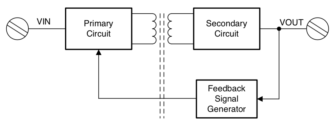
    When ISOW is powered-up, the device runs in open-loop for the first few cycles until the output reaches to >2.7V upon on which the "feedback signal generator" powers-up. Once the feedback signal generator is powered-up, it starts feeding the feedback signal to "primary circuit" to control the PWM duty cycle there by regulating the output voltage to the preset value.

    During normal operation if the input supply is momentarily turned OFF and then turned ON again, it is possible that the primary circuit is turned OFF during such brown-outs while the "secondary circuit" remains ON due to a larger output cap. Under such situations, the primary circuit may lose sync with the secondary circuit thereby leading the output to go unregulated. This situation can happen if there are input supply brown-outs that are short in duration and this situation can occur to any isolated power supply solution.

    If you have an application where the input voltage, during brown-out, is expected to drop faster than the output voltage due to additional other devices/loads at the input supply, we recommend you to address that situation by any means that can slow down input voltage drop rate compared to the output voltage drop rate. One such ways to achieve this behavior is to keep the input cap value 100µF higher than the output cap value. Please refer to section 11 of ISOW78xx datasheet for more details on the suggestions / recommendations.

    Yes, using the approach described in the tech note that you have attached would resolve this issue completely. The over voltage protection & reset circuit makes sure that the "feedback signal generator" circuit is reset whenever there is sync issue between primary & secondary circuits and the output goes unregulated.

    I hope this answers your question, let me know if you have any other questions. Thanks.

    Regards,
    Koteshwar Rao

  • Hi Koteshwar,

    Thank you very much for your prompt and detailed explanation - we didn't have additional 100uF input cap in early designs, so that explains it.

    I am using it in new designs and intend to use the over-voltage protection circuit as well.

    Thanks again,

    Goran

  • Hi Koteshwar,

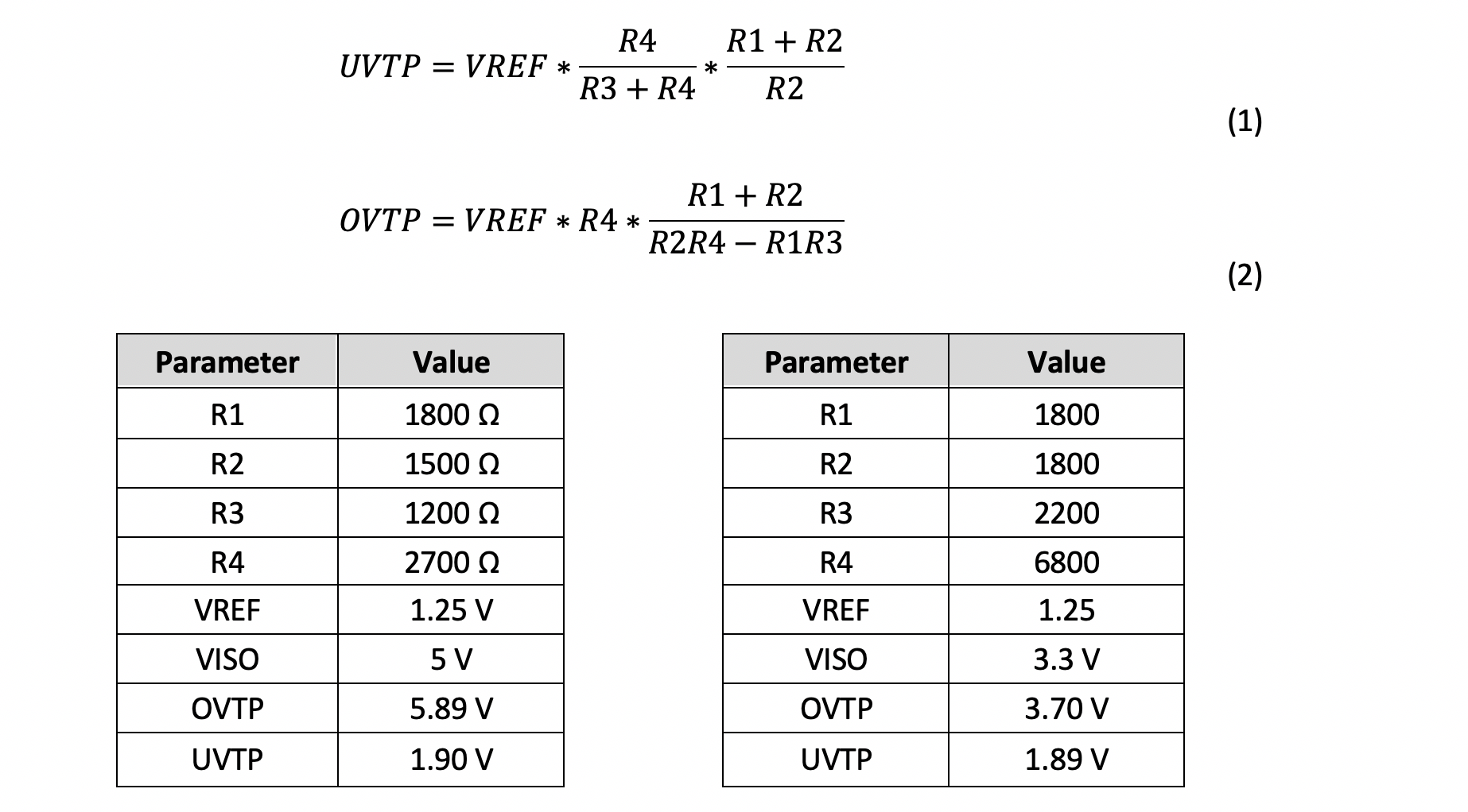
    Referring to your AN SLLA440 about over-voltage protection, the resistor values are ok for given example UVTP=1.94V (equation 1). However, if the same resistor values are used in Equation 2, the calculated OVTP=5.18V (much lower than stated OVTP=5.82V in Table 1). What is correct (resistor values or Equation 2).

    If VISO=3.3V, which values do you suggest for UVTP and OVTP?

    Thanks,

    Goran

  • Hi Goran,

    Thank you for reporting the error in calculated values from the equations and data in Table 1. The value of OVTP was calculated assuming VISO value of 6V which yields the OVTP to be as 5.82V. I see that the table lists VISO as 5V, I apologize for this error.

    I have slightly modified the OVTP equation to make it independent of VISO so that UVTP and OVTP values can be calculating using only the resistor and VREF values. Please find below the updated equations and two example tables showing resistor values for 5V and 3.3V outputs. I will also get the document SLLA440 updated accordingly. Let me know if you have any questions.

    Thanks again.

    Regards,
    Koteshwar Rao