This thread has been locked.

If you have a related question, please click the "Ask a related question" button in the top right corner. The newly created question will be automatically linked to this question.

The duration of tPOR for TPS7A6350-Q1

Other Parts Discussed in Thread: TPS7A6401-Q1

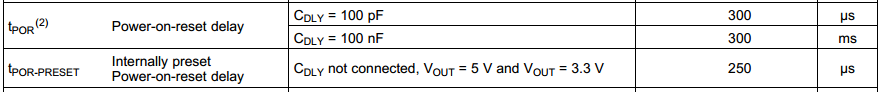
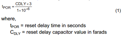
I would like to confirm the duration of tPOR for TPS7A6350-Q1.

The duration is affected by the vatiation of the capacitor value CDLY.

Are there any items of the duration? How much is the tolerance by IC itself?

I can not find the tolerance (I can find the duration of tWD by ROSC and the tolerance.).

Best regards,

Atsushi Yamauchi

  • Hi Yamauchi-san,

    tPOR is different from tWD. tPOR is the power-on-reset delay time, and tWD is the watchdog window duration.

    For the tPOR, detailed information is located in datasheet page 4 ELECTRICAL CHARACTERISTICS (continued) table and datasheet page 12 Power Up, Reset Delay, and Reset Output section. The internally preset power-on-reset delay is 250us, and customer could determine the tPOR by CDLY.


    Best regards,

    Jason Liu

  • Dear Jason-san,

    Thank you for your reply.

    I would like to know the variation of tPOR, because there are some values for typ. only and are not them for min. and max.
    And is the cause of the variation of tPOR CDLY only? Are there any cause of IC characteristics?

    Best regards,
    Atsushi Yamauchi
  • Hi Yamauchi-san,

    This spec is specified by design, not tested on ATE or bench. I need to check it with the design engineer.
    Usually, tPOR is mainly determined by CDLY when the capacitor is connected. And the bench test results could prove it.

    Does customer find any problem with the calculation or test results?

    Best regards,
    Jason Liu

  • Dear Jason-san,

    Thank you for your reply.

    Any problems does not occur. They start the check of the operation of this device.

    They check the variation of tPOR and tWD by the parts (capacitor, resister) and IC itself.

    Best regards,

    Atsushi Yamauchi

  • Dear Jason-san,

    I have additional request.
    How much are the min and max value of tWD?
    We don't need guarantee it but we want to know them.

    Or does the tolerance keep within +/-10%?
    ex. ROSC=10kohm (just this value) --> tWD: min 9ms, max 11ms
    ROSC=15kohm (just this value) --> tWD: min 13.5ms, max 16.5ms
    (ROSC=10kohm +/-5% --> tWD: min 9ms*0.95, max 11ms*1.05)

    Best regards,
    Atsushi Yamauchi
  • Hi Yamauchi-san,

    Without external capacitor, tPOR range from 136us to 282us; when Cdelay=100pF, tPOR is 167us~361us; when Cdelay=100nF, tPOR is 223ms~361ms. (Specified by design - not tested.)

    And yes, the tWD tolerance keeps within +/-10%, just like you calculation, you should also take the resistor accuracy into considered.

    Best regards,
    Jason Liu

  • Hi Yamauchi-san,

    Simulation results includes all worst cases. BTW, do you know why customer is concerning about spec tPOR?

    Best regards,
    Jason Liu
  • Dear Jason-san,

    I will confirm it.

    And I got the question.

    Can they short nRST pin and WDT_FLT pin with a pull-up resister?

    And in this case, does the specification of the threshold voltage for the reset?

    They want to use a pull-up resister for two pins.

    Best regards,

    Atsushi Yamauchi 

  • Dear Jason-san,

    I have mistaken the question for the threshold voltage.

    I rewrote those comment;

    And I got the question.

    Can they short nRST pin and WDT_FLT pin with a pull-up resister?

    And in this case, does the threshold voltage for the reset keep the specification?

    They want to use a pull-up resister for two pins.

    Best regards,

    Atsushi Yamauchi
  • Hi Yamauchi san,

    Yes, TPS7A6350-Q1 WD_FLT is an open drain output pin, and the nRST pin and the WD_FLT pin can be connected together with a pull-up resistor.
    BTW, is it able to share the customer's application block diagram and more detail project information? My mail address: jason-liu@ti.com. Thanks very much!

    Best regards,
    Jason Liu
  • Dear Jason-san,

    Thank you for your reply. 

    I will get the detail of their information (but it is difficult to get it because they don't open the detail of their product...)

    I got the questions from the customer.

    1. In term of CW, when WD pin changes from Low to high, does this IC reset (WD_FLT and nRST: Low)?

    2. In term of OW, when WD pin does not change from Low to high, does this IC reset (WD_FLT and nRST: Low)?

    In the datasheet page 17, I don't understand the operation of watchdog service for TPS7A63xx-Q1 (I understand

    it for TPS7A6401-Q1.). 

    Best regards,

    Atsushi Yamauchi

  • Yamauchi san,

    For TPS7A63xx-Q1:
    1. During CW, WD pin changes from Low to high->WD_FLT turns low for a duration of tWD_OUT->watchdog re-initializes.
    2. During OW, WD pin does not change from Low to high->WD_FLT turns low for a duration of tWD_OUT->watchdog re-initializes.
    LDO output would not be reset

    Best regards,
    Jason Liu
  • Dear Jason-san,

    Thank you for your reply.

    I have a question.

    In previous question for the short between nRST and WDT_FLT, they can do the short these pins.

    But in WD pin low -> hign, WD_FLT turns low. In this case, does nRST turn low, doesn't it?

    Are there any problems with the short (nRST and WDT_FLT) and the change  WD pin from high to low?

    Best regards,

    Atsushi Yamauchi 

  • Yamauchi san,

    If you tie nRST pin to WDT_FLT pin, low voltage signal will be detected at nRST pin when WD_FLT is low (WD pin low -> high).
    At that time, LDO output voltage keeps no change, and only nRST been pulled low.
    There is no action for the WDT_FLT when WD pin change from high to low. So there should be no problem with this connection.

    Best regards,
    Jason Liu