This thread has been locked.

If you have a related question, please click the "Ask a related question" button in the top right corner. The newly created question will be automatically linked to this question.

UC2823A ILIM pin and VMC

Other Parts Discussed in Thread: UC2823A

Hi,

At the datasheet of the UC2823A, there are two control techniques defined as VMC and CMC. 

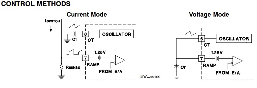
At VMC, the RAMP pin is connected to the CT pin.

At CMC, there is a slope compensation loop and some filters.

I want to understand that what will determine to turn the MOSFET off at CMC and VMC. The design is a basic buck converter at CV output.

At normal operation and, does ILIM pin give decision as to turn the MOSFET off, when it sees 1V at ILIM pin. That means MOSFET will stay at turn-on condition until ILIM pin sees 1V

Or, the IC gives decisions to turn the MOSFET off by checking feedback information from output connected INV pin and comparing it to NI pin at PWM comparator and ILIM pin serves as such a protection and normal operation ILIM must be below 1V threshold.

At normal operation and CMC technique, does ILIM pin give decision as to turn the MOSFET off, when it sees 1V at ILIM pin. That means MOSFET will stay at turn-on condition until ILIM pin sees 1V

Or, the IC gives decisions to turn the MOSFET off by checking feedback information from output connected INV pin and comparing it to NI pin at PWM comparator and ILIM pin serves as such a protection and normal operation ILIM must be below 1V threshold.

  • gG

    In Voltage mode control, when the feedback error signal intersects the ramp signal that determines the duty cycle.

    Normally the PWM comparator senses a ramp crossing a control voltage (error amplifier output) and terminates the pulse. Leading edge blanking (LEB) causes the PWM comparator to be ignored for a fixed amount of time after the start of the pulse. This allows noise inherent with switched mode power conversion to be rejected. The PWM ramp input may not require any filtering as result of leading edge blanking.

    MOSFET will turn-off when feedback signal intersect the ramp signal or when I_limit pin hits 1V. Either condition will turn-off the MOSFET.
    current limit threshold voltage is 1V and Overcurrent threshold voltage is 1.2V. When I limit pin hits 1V then the MOSFET will turn-off.
    Anytime ILIM exceeds 1.2 V, the fault latch is set and the output pins are driven low. The soft-start cap is then discharged by a 250-A current sink. No more output pulses are allowed until soft-start is fully discharged and ILIM is below 1.2 V. At this point the fault latch resets and the chip executes a soft-start.

    In current mode control, there is two loops external voltage loop as well as internal current loop. When the error signal intersects with the switch current that is added to the ramp pin, then the output pulse with terminate. A few application notes are highlighted below for additional details and to clarify the idea.

    www.ti.com/.../getliterature.tsp see application note slua111

    www.ti.com/.../technicaldocuments DN62