This thread has been locked.

If you have a related question, please click the "Ask a related question" button in the top right corner. The newly created question will be automatically linked to this question.

SN74LV1T34: SN74LV1T34

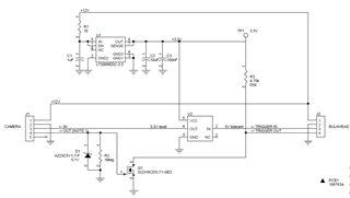
Part Number: SN74LV1T34

Hello,

I am using the above part number level shifter to downshift a 5V TTL signal to a 3.3V signal.  I've broken a few of these chips, but when I measure the input and output lines I do not see anything happening that should be damaging the chip.  The only thing I can think of is that when I turn the system off, the 3.3V VCC turns off about 0.4 sec before the 5V on the input pin.  Could this cause damage to the chip?

Thank you

  • Hey Craig,

    The input can accept 5 V safely at the input regardless of what VCC is so I don't think that would be the culprit. Can you provide a schematic of your circuit? I would like to see what type of load the device has to drive. Scope shots of operation would also help. I would like to see the frequency of the signals being passed through but also the speed of the rising and falling times to make sure the data sheet specs aren't being violated. Very slow edges could cause damage to the device, please refer to this FAQ.

  • Hi Craig,

    No, I wouldn't expect that to cause any problems.

    How exactly is the device failing when it breaks? Can you share a schematic of the device + any connected circuitry?

  • Hello Dylan,

    Sorry for not responding more quickly.  The schematic of my application is shown below.  To the left a camera assembly is plugged in, and to the right a bunch of strobe LED's to use as the camera flash.  The level shifter is only used to modify the 5V (generated by the LED's) to the 3.3V level that the camera can tolerate.  What we think is happening is that the LED's have some transient voltage event that surpasses the 7V your chip can tolerate, but we haven't been able to catch that event on a scope. We've identified a path forward to remove the level shifter from the circuit.  In the interim, I would like to know if I can count on the level shifter chip to fail with an open output. I can deal with a damaged IC, but a broken camera will be a bigger problem.  The failures we've had to date have not failed with a short between the input and output, but seem to have shorted the input to ground.  Can you say with any degree of confidence based on the internals of the chip that is will not fail in such a way that the input and output are shorted?  Thanks again for the help. 

  • Hey Craig,

    The only time I've ever seen an input - to - output short is when the input is set to a very high voltage (for example, 100 volts), then that voltage appears at all other pins of the device -- the whole thing becomes a short.

    In all other cases, the damage is limited to the pin where it happened -- with one caveat. If the input is shorted to ground, that means the output will permanently be held LOW -- or maybe HIGH, depending on the extend of the damage to the input circuitry.

    I've never seen a failed buffer with a short from input to output -- there's just too much circuitry between the two to have that happen.

  • Hi Emrys,

    Thanks for the response.  One additional question, will applying VCC to this chip without a voltage on Vin cause any damage to the chip?  I dont see anything in the datasheet that seems to say this is something to avoid, but I figured it was worth asking.

  • Hey Craig,

    There's always a voltage on the input -- if you aren't forcing it to VCC or GND, then it's floating and will likely end up at a voltage that's not ideal -- most CMOS devices have the habit of floating to about half the supply, which is basically the worst place to be. We have an FAQ that goes into details on the effects of this here: (+) [FAQ] How does a slow or floating input affect a CMOS device? - Logic forum - Logic - TI E2E support forums

  • Ok, so applying VCC and no input voltage is not a good state to leave the chip in?  What I'd like to do is disconnect the TRIGGER_IN input to the board because it is not currently used in the system.  If I'm understanding correctly, I would either need to de-populate R1, or tie Vin to ground, is that correct?

  • I'd say the best solution would be to just tie the input to ground with a large resistor -- 100k should be fine. That will prevent the input from floating and also limit power consumption during operation.