Hi expert,
Take below circuit as example.
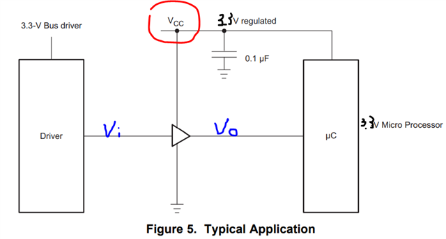
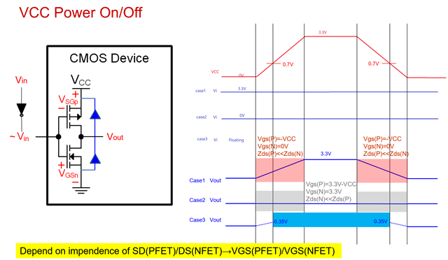
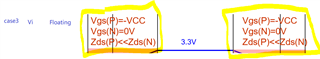
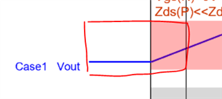
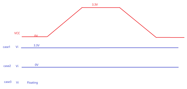
Would like to learn Vo behaviors and waveforms in below three conditions, especially care about: when VDD is very low, internal MOS doesn't work at all, what is the push-pull behavior output of Vo?
Hi expert,
Take below circuit as example.
Would like to learn Vo behaviors and waveforms in below three conditions, especially care about: when VDD is very low, internal MOS doesn't work at all, what is the push-pull behavior output of Vo?