This thread has been locked.

If you have a related question, please click the "Ask a related question" button in the top right corner. The newly created question will be automatically linked to this question.

TXS0102: Pin 8 and pin 1 signal crosstalk problem

Part Number: TXS0102


In practical application, four and five feet are suspended, 1KHZ and 1HZ 5V TTL signals are added to the eighth foot and the first foot respectively, and 1KHZ signal is found to be crosstalk to 1HZ when injected simultaneously.  Please help to analyze the cause? Any suggestions? Thank you very much!

The following is the schematic diagram and test waveform diagram

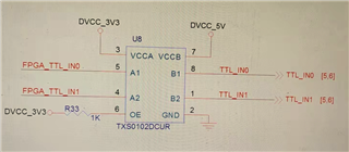
  • This diagram is the schematic diagram of the circuit used in this chip


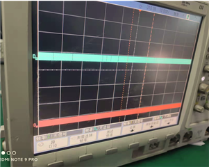
  • Oscilloscope test waveform is pin 8 and pin 1 level. This is the oscilloscope measuring board is not charged, the chip is not charged, to pin 8 and pin 1 outside the filling signal waveform;

  • This picture is the waveform of pin 8 and pin 1 after the chip is powered on.

  • Hi Rhea,

    Please note that the datasheet does not guarantee any crosstalk specifications - however the levels of this don't typically interfere with operation. Are you seeing a problem in your system caused by this noise?

    This device uses a series clamping transistor on each channel as a key component of the voltage translation circuit. These transistors all share the same bias source, and some charge-injection-based cross-talk is the result.

    If you want to minimize cross-talk with this type of translator, I would recommend to use separate devices for each channel, as this will provide a completely separate bias source for each channel.

    For more details on how the clamp transistor creates voltage translation, please see this FAQ: How do LSF (voltage clamp based) translators work?

    For more information on charge injection, there's a post on this topic here: Is charge injection causing output voltage errors in your industrial control system?