This thread has been locked.

If you have a related question, please click the "Ask a related question" button in the top right corner. The newly created question will be automatically linked to this question.

SN74LV4046A: Frequency Multiplier 0-4Hz input multiplied to 0-10kHz

Part Number: SN74LV4046A
Other Parts Discussed in Thread: CD74HC4017, , CD4046B, CD74HC4046A

I am attempting to use a SN74LV4046A PLL coupled with 4x CD74HC4017 counters to take a 0-4Hz input signal and boost that to a 0-10kHz range output. I have had very limited success at this point.  I can manage to get 100x multiplication factor by setting C1 = 10nF, R1 = 50k, R2 = no resistor but this only works in a small band near 20Hz...I need this to operate down to about 0.2Hz input with an output of 200Hz out.  I have no previous experiance working with PLLs so I do not know how to properly set them up.  Also, the datasheets on this are difficult to follow when you've never done this before. 

Am I trying to get too much bandwidth here?  Do I need to use two seperate PLLs with 100x multiplication factor each to accomplish the 1000-10000x factor I need?  Can someone tell me what Resistor and Capacitor values to use and give a quick explanation of the math involved to determine those values?

  • Hello,

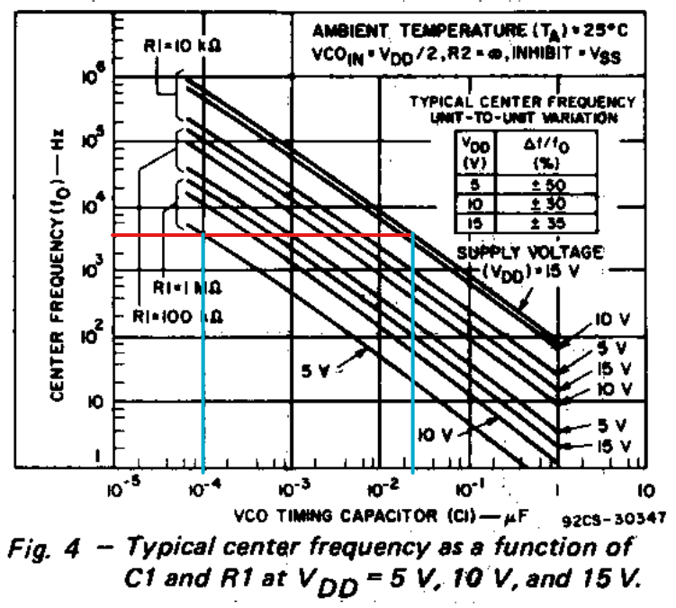
    The method to select the timing resistor and capacitor is just to follow the graph in the datasheet.

    To get 4 kHz center frequency (highlighted above in red), you can select any resistor + capacitor combo that intersects with a 5V line. I think the easiest pick would be 1000pF + 100 kohm, which falls right in the middle. To stretch that up to 10 kHz center freq, you could go to either a smaller capacitor or resistor - typically it's easiest to change out the resistor, so I would try going to a 33kohm and see what happens.

    One very important thing to note here is that your feedback loop to control the VCO is filtering a _very_ slow signal (0 to 4 Hz), so your LPF also needs a very low corner frequency, and thus you will have a very slow system response.  Right now your feedback loop filter is set for a 3dB corner frequency of 1.5 Hz, which is too high. You will need to be about 10x below the minimum frequency of operation -- let's say you want to operate down to 0.1 Hz, then the loop filter will need a corner frequency of 0.01Hz, and thus your filter components could be 159kohm + 10uF.

    Here are a few additional app notes that may come in handy for you:

    CMOS Phase-Locked-Loop Applications Using the CD54/74HC/HCT4046A and CD54/74HC/HCT7046A

    Implementation of FSK Modulation and Demodulation using CD74HC4046A

    Generating Low Phase-Noise Clocks for Audio Data Converters from Low Frequency Word Clock

    Also, there are other '4046 devices that are more optimized for 5V operation -- the one you're using was designed for 15V operation. My top pick would be SN74LV4046A, although the datasheet is a bit lacking in details. The CD74HC4046 has a much better datasheet - fortunately, most of the data is interchangable, so you can use that for reference.

    Edit: My mistake - I saw CD4046B and forgot you said you're using LV4046.

  • Thank you, that was very helpful.  I see you're suggesting 100kohm for R1, doesn't the datasheet for the SN74LV4046A say R1 should be a max of 50k?

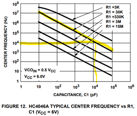
  • Ah yes - I was going off the CD4046B datasheet. I would expect the lv4046 to work there as well -- most likely that limit is to maintain linearity that's promised in the DS. Considering that, a better solution would be to just stick to the values they have and adjust the capacitor instead. You should see a log-linear relationship between the capacitor value and frequency of operation, so you can estimate a value that should work.

    Arbitrarily selecting 30k (to be in the middle of the range) from the CD74HC4046A datasheet:

    I'd try out 30k and 0.01uF to start.

  • I have replaced R1 with 33.2k, C1 with 10nF, and the filter components with 160k and 10uF.  if I put 4Hz in and give it 1000x multiplication factor it seems to multiply the signal but it bounces around for about  a min or two before finally settling and locking in at 4kHz out (see attached video), If I reduce this to 1Hz in it does something similar except it never settles or locks in and the signal seems to come and go as well as bouncing around (see attached video).  Is this the filter components not filtering properly? 

  • I'd recommend to take a look at the VCO input, after the filter, and set your scope to a very slow time scale (1s or slower per division) This will likely show how the filter output appears.

    I'm curious -- why take this approach to this solution -- wouldn't an MCU be much smaller, cheaper, and more accurate/efficient?

  • I am taking this approach because the STM32 MCUs we use are very hard to come by in the market right now. Also, we want to avoid any software developement that goes with it.

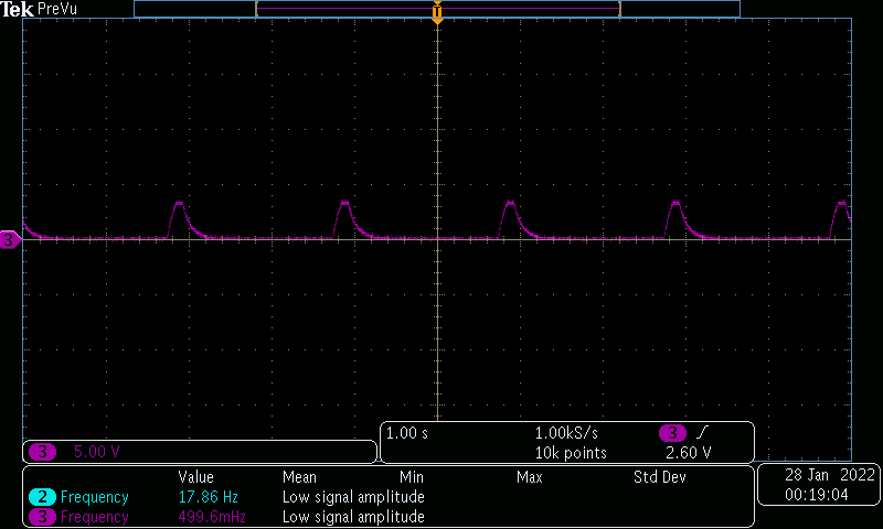
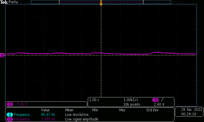
    I have taken some screen captures of the VCO input (post filter) and this is what I have

    Fc = 1.5Hz (47kohm w/ 2.2uF)

    Fc = 99.47mHz (160k w/ 10uF)

    Fc = 40mHz (402k w/ 10uF) 

    Not sure what exactly I want to see here.  Are the humps in the first picture good or bad?  What am I supposed to be shooting for? According to the SN74LV4046A datasheet it suggests R = 1kohm and C = 1uF on page 13 in table 1.

  • I can understand both the availability and the difficulty issues with MCUs.  You might consider a simpler MCU for this as a dedicated solution though - it will give far better results in my opinion.

    -

    As for what you're looking for at the VCO input -- if you want a stable output, then you want a stable input. The VCO input directly represents the output frequency, so if you want a stable output frequency, then the input needs to be stable.

    I can see in your second scope shot that you're starting to get there with 160k + 10uF, but it still has some very pronounced bumps to it. With an analog solution, there's always going to be some ripple here -- you can keep increasing the RC to get a smooth signal, but the response time will likely be measured in minutes.

    With the MCU approach, you just count the time between edges (don't even need a full waveform) and then set the output to the appropriate frequency -- basically zero setup time, and it's going to be rock solid on the desired frequency.

  • So should the VCO input be a square wave or a DC voltage?  Or should it be flat like you see with the 402k resistor and 10uF capacitor?  Both the 160k and 402k resistor circuits don't seem to settle, or do I just need to watch them for several minutes till they settle?  Obviously a settling time of several minutes is not going to be acceptable.  Is there a way to get this to settle faster or this this inherent to working with such a low frequency as an input?

  • The VCO input should be DC -- For example, if you want the center frequency to be output, the input to the VCO should be VCC/2.

    It is possible to get faster settling low-pass filters that have the same cutoff frequency from active filtering, but that's really beyond the level of help I can provide.

    I just don't think this will be a good solution for you.

  • So right now our center frequency with 33.2k and 10nF looks to be approx. 10kHz.  By definition this should mean then that this will work at some bandwidth around 10kHz.  For my application 10kHz is the highest I'd want this to work.  How do I calculate the bandwidth?  If the maximum frequency is 2fc then we could set this at 5kHz and maybe it would stabilize better/faster at lower input frequencies?  Or do this not have a bearing on the settling time?

  • You can set the frequency range to be smaller, and that will help some, but the major issue I see is with the filter -- you still have to filter the 1 Hz signal to get a stable VCO input.

    With a 402k and 10uF filter, it looks like the settling time is about 10 seconds, and the ripple ends up being around 300mV.

    For example, let's say this device is perfectly linear and you get the voltage range of 0 to 5V to have _exactly_ the right frequency range (0 to 10 kHz), now you have this relationship:

    Fout = VCO_in * 2000

    With the above filter, your output will vary from ~4680 Hz to ~5300 Hz when the input is 1 Hz.  Would this be acceptable?

    Something else to mention is that devices like this won't be perfectly linear at the edges of operation (near 0V and near VCC), so I'd make that range a little bigger than what you need.

  • Yeah, that kind of variation would not be acceptable.  In reality we need to be able to work from approx. 200mHz - 4Hz input and have that output 1000x is there a different/better way to do this does that does not involve an MCU? Would breaking this into two stages and using 2 PLLs (one for low frequencies and one for higher frequencies to to take the input all the way up to the kHz range) cut down on this ripple and make it more sable?

  • I'm afraid I don't know of any better approach. Breaking up the PLL into stages only adds issues -- you still have to filter out that 200mHz signal at some point, and the output of that will directly control a VCO somewhere.

    I did mention using active filtering earlier. You could, for example, design a high order active filter that could give you a faster response and less ripple in the output, but it's going to be much more complicated and expensive than just getting a $0.25 MCU and programming it with a few lines of code -- and the results won't be as good.