This thread has been locked.

If you have a related question, please click the "Ask a related question" button in the top right corner. The newly created question will be automatically linked to this question.

SN74LVC1G74: Use tact switch as power button and add thermal sensor

Part Number: SN74LVC1G74
Other Parts Discussed in Thread: SN74LVC2G17, , SN74LVC1G08

Hi sir 

Our design is a 19V DC in, so I use the BJT to transfer the voltage to 5V.

And this project need to use the tact switch as the power button, 

so we try to use the SN74LVC1G74 and SN74LVC2G17 to implement this function.

And we need the thermal sensor(over temperature will pull down at OS/ALERT pin) to do the thermal cutoff, 

so we add the SN74LVC1G08 to combine the signal from power button and the thermal sensor.

Could you help to review whether this design can workable?
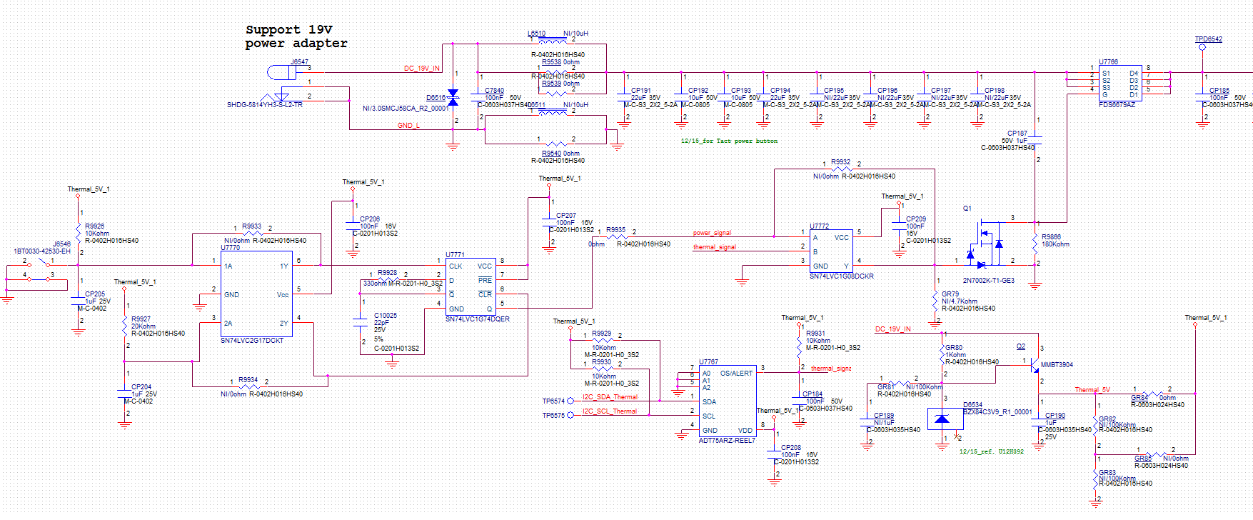
Thanks.

  • The switch circuit generates a falling edge when pressed, and a rising edge when released. The SN74LVC1G74 triggers on the rising edge. Maybe you want to exchange R9926 and CP205.

    What is the purpose of R9928? In front of a high-impedance input, it has no effect.
    What is the purpose of C10025? It just increases the load on /Q.
    You can connect /Q directly to D.

  • Hi sir

    If I exchange R9926 and CP205, what kind of waveform will be generated when the power button is pressed?

    R9928 and C10025 are RC delay for the D input, you can refer to the datasheet of SN74LVC1G74.

    But the purpose of RC delay of R9928 and C10025, I also want to check with TI. 

    If you have any idea, could you share for me?

    Thanks.


  • If you exchange R9926 and CP205, then the switch circuit generates a rising edge when pressed, and a falling edge when released.

    If you want an RC delay for the D input, then you have to move R9928 to the /Q pin. But you do not need a delay here, you can connect /Q directly to D.