Other Parts Discussed in Thread: TXU0304, TXB0104

This thread has been locked.
If you have a related question, please click the "Ask a related question" button in the top right corner. The newly created question will be automatically linked to this question.

Thanks for your reply!
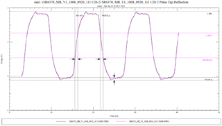
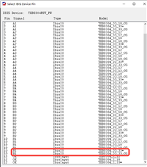
How to select IO_33 and IO_33_OS during simulation? According to the simulation results, other conditions are the same (topology: Level Shift-CPU), the waveform is abnormal when IO_33 is used(Fig.1), and the correct waveform can be obtained only when IO_33_OS is used(Fig.2).

Fig.1 TXB0304_IO_33

Fig.2 TXB0304_IO_33_OS
Hi,
Select IO_33 if the drivers have sufficient drive; as the IO when the one shot is activated has a lower output impedance for higher output drive.
Furthermore, we wouldn't typically recommend auto bidirectional devices for applications that are not auto bidirectional due to their design nature for little to no drive strength; to help the drivers override them for auto sensing, as well as their sensitivity to external components. Hence, TXU0304 is a more suitable recommendation for SPI, thanks.
Best Regards,
Michael.
I'm sorry that the maps in the above problem are TXB0304_IO_18 and TXB0304_IO_18_OS, but the simulation error occurs when the TXB0304_IO_33 model is used in the downlink, and only TXB0304_IO_33_OS can be used. Is this also because it has little or no driving strength?
2. If the QSPI module is used, is TXB more suitable? According to the datasheet, the configurations of TXB0104 and TXB0304 are similar. Is the driving capability of TXB0104 better than that of TXB0304 because the simulation and test results are better?
Thanks, looking forward to your reply~
Hi,
I'm sorry that the maps in the above problem are TXB0304_IO_18 and TXB0304_IO_18_OS, but the simulation error occurs when the TXB0304_IO_33 model is used in the downlink, and only TXB0304_IO_33_OS can be used. Is this also because it has little or no driving strength?
Just to double confirm, are not using the IO_without_OS and the IO_with_OS independently as they are meant to be used together as one for simulations, right?
2. If the QSPI module is used, is TXB more suitable? According to the datasheet, the configurations of TXB0104 and TXB0304 are similar. Is the driving capability of TXB0104 better than that of TXB0304 because the simulation and test results are better?
Furthermore, I would recommend TXB0104 for QSPI while keeping your capacitive loading and traces as minimal as possible, thanks.
Best Regards,
Michael.
I'm sorry that the maps in the above problem are TXB0304_IO_18 and TXB0304_IO_18_OS, but the simulation error occurs when the TXB0304_IO_33 model is used in the downlink, and only TXB0304_IO_33_OS can be used. Is this also because it has little or no driving strength?
Just to double confirm, are not using the IO_without_OS and the IO_with_OS independently as they are meant to be used together as one for simulations, right?
I don't know if I understand you correctly, but you can only choose between IO_without_OS and IO_with_OS for emulation

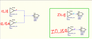
Our simulation is shown in the green box(Whether this modeling method is correct?). Normal waveform can be obtained only when IO_with_OS is used, which should be related to its strong output drive.However, the link cannot run when using TXB0304_IO_33, so I want to confirm whether it is related to no or weak drive strength.
Finally, I would like to confirm whether the "OS" in the actual application will automatically open when the driver is not enough or needs to be configuredThanks
Hi Liwenting,
Our simulation is shown in the green box(Whether this modeling method is correct?). Normal waveform can be obtained only when IO_with_OS is used, which should be related to its strong output drive.However, the link cannot run when using TXB0304_IO_33, so I want to confirm whether it is related to no or weak drive strength.
I am not sure the "green box" being referred to. However, it is related as the IO_with_OS has a higher output drive.
Finally, I would like to confirm whether the "OS" in the actual application will automatically open when the driver is not enough or needs to be configured
Note that it will not automatically open when the driver is weak; as the device is designed to be overridden by the drivers for directional auto-sensing. The OS is designed to momentarily activate to improve switching speeds only when a rising or a falling edge is detected, and designed to stay on for about 10 ns to 30 ns; once deactivated, the internal buffer resistor of the TXB device continues driving the line high and maintains its’ steady state. See "A Guide to Voltage Translation With TXB-Type Translators".
Please note that this applies to all auto bidirectional devices in general (i.e designed to be weak for the drivers to override them for directional auto sensing) and the TXU recommendation is better suited for fixed directional SPI applications, thanks.
Best Regards,
Michael.
Our simulation is shown in the green box(Whether this modeling method is correct?). Normal waveform can be obtained only when IO_with_OS is used, which should be related to its strong output drive.However, the link cannot run when using TXB0304_IO_33, so I want to confirm whether it is related to no or weak drive strength.
I am not sure the "green box" being referred to. However, it is related as the IO_with_OS has a higher output drive.
I'm sorry I forgot to put the picture,Whether this modeling method is correct?Thanks~
