This thread has been locked.

If you have a related question, please click the "Ask a related question" button in the top right corner. The newly created question will be automatically linked to this question.

TXB0304: QSPI Trace limitation and evaluation of one short level-shift

Part Number: TXB0304

We use TXB0304 to transfer 33MHz and 16MHz CLK from 1V8 to 3V3.

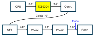
The topology list show as below:

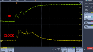
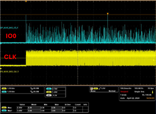
Topology 1: QSPI 16MHz trace length is 14" after level-shift, the waveform of CLK can't be recognized.

 Is there any solution to support topology 1 with trace limitation suggestion? Or how to evaluate topology with small function change 

Thank you

  • What matters is the capacitance. The total capacitance of the traces, connector, and cable is too high for the TXB.

    QSPI (and TXB level shifters) cannot be used over long distances; you have to put the devices near each other on the same board. It is possible to get high speed over longer distances with protocols such as LVDS or PCIe, but those use unidirectional, differential signals and are not compatible with QSPI.

  • Hey Chu-Chen,

    In addition to Clemens' response, you may refer to section 11 of the datasheet for best layout practices. 

    Regards,

    Jack 

  • Hi Clemens

    I got that the capacitance and trace length should be shorter

    We are still doing the experiments to see how long of trace can solve this question.

    And here is the new waveform for 16MHz probe on same location but still can't boot up the flash

    Without shorten the total trace, if there any solutions to eliminate the ringing effect?

    Thanks

  • Hi Jack

    OK, we already checked the layout guideline, thank you!

  • Hi Clemens

    I tried to simulate the full QSPI topology with txb0304.ibs (IO_33_OS pin) to check the ringing effect.

    But I found that the simulation is not similar with our testing waveform result.

    Can this txb0304.ibs model be used for one short function loading simulation?

    Or do you have any suggestion for simulation to approach the real case.

    Thank you

  • What capacitance and inductance did you use in the simulation?

  • Hi Clemens

    The total capacitance is about 100 pf

    Inductance include in transmission line 14"

    Thanks 

  • You forgot the cable. The total length is about 24", and the capacitance is much higher.

    As far as I know, the IBIS model cannot show that the edge accelerator times out after a few nanoseconds.

    And no simulation will help; neither QSPI nor TXB can be used over long distances.

  • Hi Clemens

    What's the detailed of "IBIS model cannot show that the edge accelerator times out after a few nanoseconds"

    I check the document "scea131.pdf", it shows that with one-shit only have 1.7ns rise/fall time, so the round-trip delay need to be in 10~30ns, is it right? 

    Thank you

  • The TXB essentially has two different outputs, with and without the one-short. The TXB switches between them, but the IBIS model has two separate models.

  • Hi Clemens

    Two more question:

    1. In TXB document, it said that "if the capacitive loading is larger that 70pF, the O.S. will time-out after 10 ns and the output will continue to rise of fall based on the RC time constant determined by the 4-kΩ buffer, load resistance and capacitive loading.", may I have the formula or more detail to describe the oscillation? How can I evaluate topology caused by quality of impedance mismatch or loading is too heavy?  


    2. I want to make a conclusion of TXB routing rule in real number

    In the document TI suggest to control total Cload need to < 70pF with short trace length

    If I have the new case, all components Cload is about 35pf, but the trace length is already 12", I think the total Cload may be about 70pf, but how can we judge the marginal case will be pass without simulation

    May I have your comment about it, if you can provide real number rule will be better

    Thank you 

  • 1. There is no oscillation; the R-C low-pass filter slows down the edges. See Wikipedia.

    2. I do not know the characteristics of your board. The easiest way to check might be to just measure the waveforms.