This thread has been locked.

If you have a related question, please click the "Ask a related question" button in the top right corner. The newly created question will be automatically linked to this question.

SN74LVC1G123: DEMODULATOR CIRCUIT FOR IR SIGNAL

Part Number: SN74LVC1G123

We have used IC [MPN:- SN74LVC1G123YZP] for demodulation of IR signal so

1. please review this circuit and provide confirmation that it is right part for this application
2. and also share you feedback on review the circuit.


Check below example waveform of
Waveform 1 --> Signal name=IR_SIGNAL_IN [Modulated IR signal coming from IR Receiver sensor] &
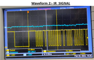
waveform 2 --> Signal name=IR _Signal [Output of the SN74LVC1G123YZP IC [Pin-5] which is Demodulated IR signal ] 
IR Receiver Part:- TSMP1138 [PFA datasheet]
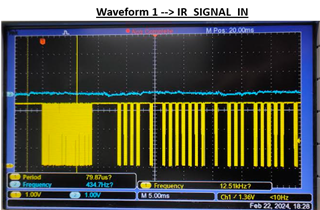
TSMP1138-Vishay.pdf

  • The TSMP1138 outputs a 38 kHz square wave, so the length of a cycle is about 26 µs. The pulse length should be somewhat longer than that, e.g., 47 µs, which could be achieved with C = 1 nF, R = 47 kΩ.

    Your timing R/C values result in a pulse length of about 22 ms. Why did you choose this value?

  • Hii Clemens,

    Thanks for feedback.

    We have miscalculated the value. So we are considering C = 1 nF, R = 47 kΩ value and update the design accordingly.

  • 22 ms is much longer than necessary, but it can work if it is much shorter than the pulse length of your actual signal. The second waveforms might be OK. Is there an actual problem?

  • Not actual problem, We are currently design phase and actually we didn't tested circuit yet so we need R & C value in design to get second waveform from waveform 1. And you already provided C = 1 nF, R = 47 kΩ So again reverify this value is ok for demodulation of IR_SIGNAL_IN as per given waveform so we will consider in this design.

  • I agree with Clemens here. Those values will work for this design + probably save costs significantly on the capacitor.