This thread has been locked.
If you have a related question, please click the "Ask a related question" button in the top right corner. The newly created question will be automatically linked to this question.
Tool/software:
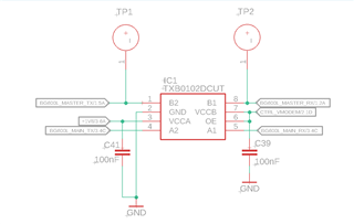
I recently added TXB0102 to make the UART level translation from an MCU at +3.3 V (PIC18F47J13) to send AT Commands to a Modem at +1.8 V (Quectel BG600L-M3), however, in my design I have the MCU in the B side of the translator and the Modem in the A. Could this cause any issues?
As well, the OE and VCCB are coming together from a GPIO of the MCU while VCCA is coming from a +1.8V pin from the modem itself.
You have one signal in each direction. The TXB does not care which of these chips is called "MCU" or "modem".
The OE pin is overvoltage tolterant, so you can use a 3.3 V signal.
You say that VCCB is for the MCU, but the label is "CTRL_VMODEM". Is this correct?
Your signals are not bidirectional. You should use the TXU0202 instead.
You say that VCCB is for the MCU, but the label is "CTRL_VMODEM". Is this correct?
Yes. It's a GPIO from the MCU that is labeled like that beacuse it also enables a DC-DC that supplies the power to the Modem. The GPIO is 3V3 when HIGH and 0V when Low (as well there is a pull down resistor in this line).
Your signals are not bidirectional. You should use the TXU0202 instead.
Is this critical in this case? Why?
It's not critical, but the TXB is optimized for bidirectional signals, so it is much less robust and does not work with long traces or pull-up/-down resistors.