


Tool/software:
Hi,
I am Using SN74HC595 ic for my ongoing Project in cascading connection, after fixing or not fixed the hardware.
Can anyone give me some help on this. It is now critical situation on the project.
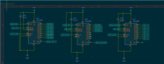
I am using this Schematic for my project,
Project Detailing
U14 is controlling the Negative Side of the Motor.
U12 & U13 is controlling the Positive side of the Motor.
Should I have used different pin for my SN74HC595 ic or Single Data pin is Ok.
I am Sharing the Code What I used with the
/*
* Hardware Connections:
* Vin - 5V for SN74HC595 and MCP3208
* GND - Common ground
* SN74HC595 ST_CP - Pin 19 (ESP32)
* SN74HC595 SH_CP - Pin 18 (ESP32)
* SN74HC595 DS - Pin 16 (ESP32)
* MCP3208 SPI CS - Pin 15 (ESP32)
* MCP3208 SPI CLK - Pin 14 (ESP32)
* MCP3208 SPI MOSI - Pin 13 (ESP32)
* MCP3208 SPI MISO - Pin 12 (ESP32)
*/
#include <SPI.h>
// Pin Definitions for Shift Registers
const int latchPin = 19; // Latch (ST_CP)
const int clkPin = 18; // Clock (SH_CP)
const int dtPin = 16; // Data (DS)
// MCP3208 SPI Pins (HSPI)
const int MCP3208_CS = 15; // Chip Select for MCP3208
const int MCP3208_CLK = 14;
const int MCP3208_MISO = 12;
const int MCP3208_MOSI = 13;
SPIClass *hspi = NULL;
// Shift Register Data
byte positiveMotorState1 = 0xFF; // Motors 1-8 (Shift Register #1) - Initially All High
byte positiveMotorState2 = 0xFF; // Motors 9-16 (Shift Register #2) - Initially All High
byte negativeMotorState = 0xFF; // Motors negative terminals (Shift Register #3) - Initially All High
// Function Prototypes
int readMCP3208(byte channel);
void updateShiftRegisters();
void controlMotor1(bool state);
void setup() {
Serial.begin(115200);
// Define shift register pins as output
pinMode(latchPin, OUTPUT);
pinMode(clkPin, OUTPUT);
pinMode(dtPin, OUTPUT);
// Define MCP3208 chip select pin as output
pinMode(MCP3208_CS, OUTPUT);
digitalWrite(MCP3208_CS, HIGH); // Ensure the chip is deselected
// Initialize HSPI for MCP3208
hspi = new SPIClass(HSPI);
hspi->begin(MCP3208_CLK, MCP3208_MISO, MCP3208_MOSI, MCP3208_CS);
// Update all registers initially
updateShiftRegisters();
}
void loop() {
// Read analog value from MCP3208 channel 0
int adcValue = readMCP3208(0);
Serial.print("MCP3208 Channel 0 Feedback Value: ");
Serial.println(adcValue);
// Feedback logic for Motor 1
if (adcValue < 100) { // Threshold for feedback
Serial.println("Feedback below threshold! Turning OFF Motor 1.");
controlMotor1(false); // Automatically turn OFF Motor 1
} else {
Serial.println("Feedback sufficient. Motor 1 remains ON.");
controlMotor1(true); // Turn ON Motor 1
}
delay(1000); // Delay to avoid rapid changes
}
// Function to control Motor 1
void controlMotor1(bool state) {
if (state) {
bitSet(positiveMotorState1, 0); // Turn ON positive side for Motor 1
bitSet(negativeMotorState, 0); // Turn ON negative side for Motor 1
} else {
bitClear(positiveMotorState1, 0); // Turn OFF positive side for Motor 1
bitClear(negativeMotorState, 0); // Turn OFF negative side for Motor 1
}
// Update shift registers after state change
updateShiftRegisters();
}
// Function to update cascading shift registers
void updateShiftRegisters() {
digitalWrite(latchPin, LOW); // Prepare for data transfer
// Send data to the third (negative-side) register first
shiftOut(dtPin, clkPin, MSBFIRST, negativeMotorState);
// Send data to the second (positive-side) register
shiftOut(dtPin, clkPin, MSBFIRST, positiveMotorState2);
// Send data to the first (positive-side) register
shiftOut(dtPin, clkPin, MSBFIRST, positiveMotorState1);
digitalWrite(latchPin, HIGH); // Latch data
}
// Function to read from MCP3208 ADC
int readMCP3208(byte channel) {
if (channel > 7) return -1; // Invalid channel
// Prepare SPI communication
byte command = 0b00000110 | ((channel & 0x04) >> 2); // Start bit + single-ended
byte secondByte = (channel & 0x03) << 6; // Channel configuration
digitalWrite(MCP3208_CS, LOW); // Select MCP3208
hspi->beginTransaction(SPISettings(1000000, MSBFIRST, SPI_MODE0));
hspi->transfer(command); // Send first byte
int result = (hspi->transfer(secondByte) & 0x0F) << 8; // Send second byte and receive response
result |= hspi->transfer(0x00); // Receive remaining bits
hspi->endTransaction();
digitalWrite(MCP3208_CS, HIGH); // Deselect MCP3208
return result;
}
what I want Q14 always on HIGH , but i want to control Q13 and Q12 Control by User.
regards
Saurav

