A related question is a question created from another question. When the related question is created, it will be automatically linked to the original question.
If you have a related question, please click the "Ask a related question" button in the top right corner. The newly created question will be automatically linked to this question.
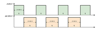
Thank you for your reply! But can the rising edge I need to output correspond to the falling edge of the input, and also generate a square wave with duty=1.5 * A?
I can use two 3058.syscfg to complete this function, but due to hardware delay, the final output waveform duty will be greater than 2 * A. Is there a better way to achieve this function, such as a counter and PWM generator?
By hardware delay, you mean propagation delay? I think the best way is to just adjust the counter data/counter clock frequency until it gets the duty cycle you want.
You could use a PWM generator, but to get a 2*A duty cycle you'd probably have to use I2C to set the counter data to what you want it to be in real time, with KEEP tied to VCC so that the data doesn't change except through I2C.
Thank you very much for your reply. We do not want to use I2C to control the output duty cycle in real time. If the above logic is difficult to implement, is there a way to implement the following logic:
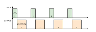
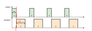
The duty cycle of the input signal is variable, and the duty cycle of the output signal needs to change along with it. The maximum duty cycle of the output signal is twice that of the input signal, while the output duty cycle of this device is fixed, which is different from my requirements. And when the input signal is high, the output signal must be low, and the above solution does not meet this requirement. You can refer to my previous question for requirements
How close to the falling edge of the signal does the output need to be? Does it matter if there is some space between the falling edge of the input and the rising edge of the output, for example ~200us? A DFF can be used to phase shift the output, but otherwise I'm finding it difficult to meet the requirement that the output starts at the falling edge.
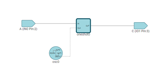
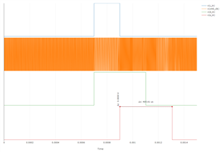
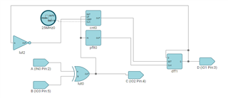
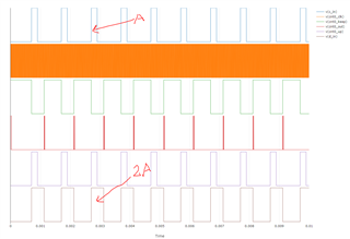
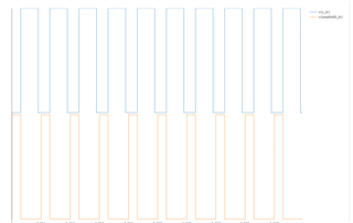
Try this circuit. I duplicated it and added some extra logic. Maybe this is what you did earlier. You just need to adjust counter data and clock speed to get the duty cycle you want. Here is an example simulation:
Yes, the output pulse width is very slightly longer than 2A (by 7us, or about 7 clock cycles because of how the counters work). Basically, the output pulse will always be ~3.5% longer than 2A (i.e. final output will always be 2.035A). Hopefully this is margin is ok with your specifications. If it is not, then I do not see a good way to achieve this with TPLD. There's always going to be a slight delay
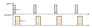
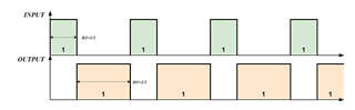
For you other scenario with duty cycle <1/3, =1/3, >1/3, we can achieve this, but it's going to be similar where the end pulse width is always slightly longer than you want it to be.


 https://e2e.ti.com/cfs-file/__key/communityserver-discussions-components-files/151/pulse2.syscfg